Heat dissipation device

a heat dissipation device and heat dissipation tube technology, applied in the direction of basic electric elements, semiconductor devices, lighting and heating apparatus, etc., can solve the problems of poor levelness on the back side of the base, difficult to control the depth of s-shaped and u-shaped grooves, and heavy weight, so as to reduce manufacturing costs, excellent levelness, and the effect of reducing materials

Active Publication Date: 2019-04-02
ASIA VITAL COMPONENTS SHENZHEN CO LTD
View PDF18 Cites 1 Cited by
  • Summary
  • Abstract
  • Description
  • Claims
  • Application Information

AI Technical Summary

Benefits of technology

[0006]To solve the above problems, a primary object of the present invention is to provide a heat dissipation device that includes a substrate and at least one heat pipe, which is pressed to tightly fit in a receiving groove defined by the substrate to tightly connect the substrate to have an excellent levelness on a top and a bottom side of the substrate.
[0007]Another object of the present invention is to provide a heat dissipation device that can be manufactured at lower manufacturing costs with reduced materials and further provide uniform temperature effect.
[0008]To achieve the above and other objects, the heat dissipation device provided according to the present invention includes a substrate and at least one heat pipe. The substrate has a top and a bottom side, and internally defines a receiving groove, which is used for the heat pipe to be tightly fitted therein, and extended through the top and the bottom side of the substrate. The heat pipe has a first, a second, a third, and a fourth side, wherein the first and the second side are opposite to each other, whereas the third and the fourth side are opposite to each other. Moreover, the first and the second side of the heat pipe are respectively flush with the top and the bottom side of the substrate, whereas the third and the fourth side are pressed to tightly in contact with two opposite inner walls of the receiving groove to tightly connect the substrate to the heat pipe. With these arrangements, the substrate has an excellent levelness on a top and a bottom side thereof, and can be manufactured with reduced materials to maintain light weight, so as to provide uniform temperature effect.

Problems solved by technology

However, it is hard to control the S-shaped and the U-shaped groove depth and apt to cause tolerance problem.
Also, when being processing, it is also apt to cause a poor levelness on a back side of the base due to releasing stress, such that the S-shaped and the U-shaped groove respectively have a top and a bottom side that are unlikely to tightly contact with the cooling fins or heat-generating elements, such as central processing units (CPUs) or graphics processing units (GPU).
In addition, since the base is made of copper, it has a heavy weight.
In brief, the conventional heat dissipation device has the following disadvantages: (1) being heavy weight; (2) wasting materials; (3) having tolerance problem in groove; and (4) having a poor levelness on a bottom side of the base.

Method used


Image

  • Heat dissipation device
  • Heat dissipation device
  • Heat dissipation device

Examples


Embodiment Construction

[0030]The present invention will now be described with some preferred embodiments thereof and by referring to the accompanying drawings. For the purpose of easy to understand, elements that are the same in the preferred embodiments are denoted by the same reference numerals.

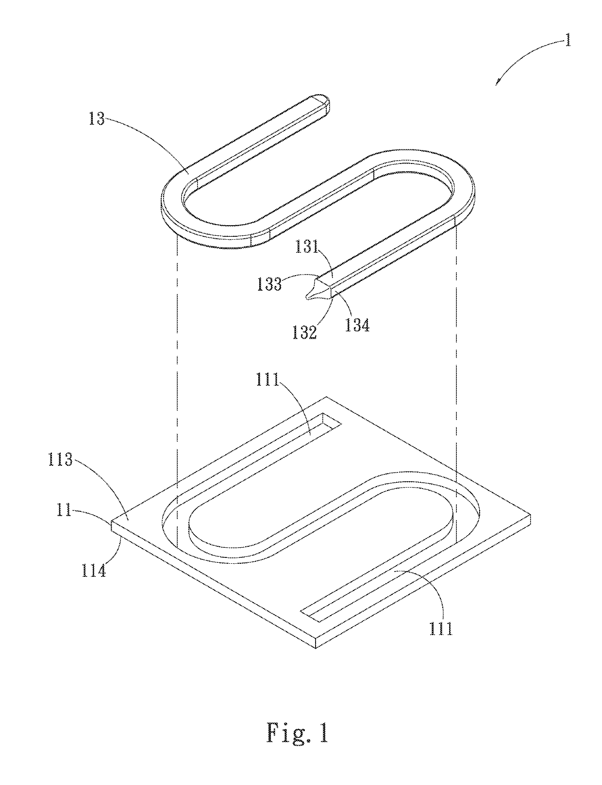
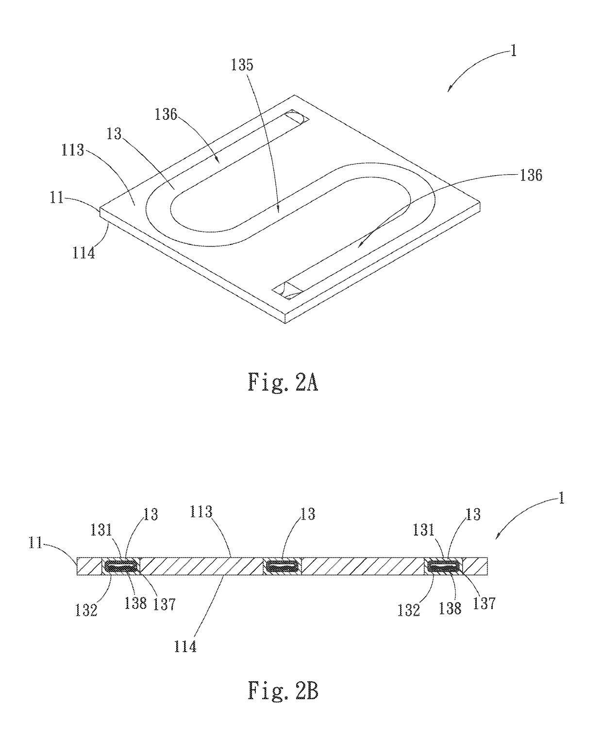
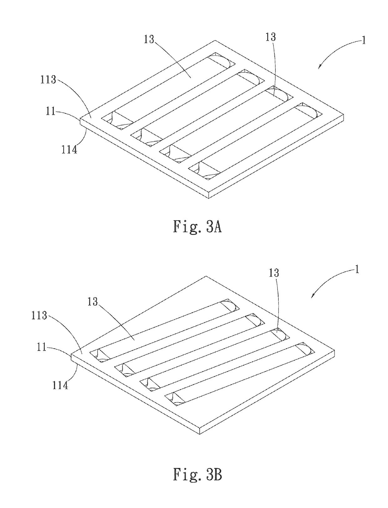
[0031]Please refer to FIGS. 1, 2A, and 2B, which are exploded, assembled perspective views, and assembled sectional view, respectively, of a heat dissipation device 1 according to a first preferred embodiment of the present invention. As shown, the heat dissipation device 1 includes a substrate 11 and at least one heat pipe 13. The substrate 11 is made of a metal material, such as copper, and internally defines at least one receiving groove 111 extended from a top side 113 through a bottom side 114 of the substrate 11. In the illustrated first preferred embodiment, the receiving groove 111 can be, for example but not limited to, curved-shaped, such as S-shaped. In implementation, the shape of the receiving groove...


PUM


Abstract

A heat dissipation device includes a substrate and at least one heat pipe, which is pressed to tightly fit in a receiving groove defined by the substrate to make two opposite lateral sides of the heat pipe tightly respectively in contact with two opposite inner sides of the receiving groove to tightly connect the substrate to the heat pipe to solve the problem existing in the conventional heat dissipation device of a poor levelness of the receiving groove on a top and a bottom side of the substrate, so as to have reduced manufacturing costs and provide uniform temperature effect.

Description

FIELD OF THE INVENTION[0001]The present invention relates to a heat dissipation device, and more specifically, to a heat dissipation device that is capable of effectively controlling a receiving groove depth to maintain the levelness of a substrate on a top and a bottom side, so as to provide a uniform temperature effect.BACKGROUND OF THE INVENTION[0002]As rapid advance in information and electro-optical industry, electronic products have been largely upgraded and thinned in the recent years. Under the requirements of high speed, high frequency, and miniaturization, the density of heating of the electronic elements is higher and higher, so heat dissipation efficiency has become one of the key factors to determine the stability of electronic products. Since both heat pipes and heat conducting fins have high heat conductivity, they are widely used to dissipate heat in various electronic products. Both heat pipes and heat conducting fins dissipate heat mainly through a wick structure m...

Claims


Application Information

Patent Timeline
Patent Type & Authority Patents(United States)
IPC IPC(8): F28D15/00H01L23/427F28D15/02F28F3/02H01L21/48
CPCF28F3/02F28D15/0233H01L23/427H01L21/4882F28D15/0275
Inventor LIN, SHENG-HUANGLIN, YUAN-YI
Owner ASIA VITAL COMPONENTS SHENZHEN CO LTD
Why Eureka
Try Eureka