Check patentability & draft patents in minutes with Patsnap Eureka AI!

Dynamic azimuth scanning for rotating active electronic scanned array radar

Active Publication Date: 2019-04-16
RAYTHEON CO
View PDF35 Cites 7 Cited by
  • Summary
  • Abstract
  • Description
  • Claims
  • Application Information

AI Technical Summary

Benefits of technology

The patent describes a radar system that uses a dynamic electronic azimuth beam steering to control the rate of forward or back scan at different destinations based on information about the weather and other environmental conditions. This allows for more uniform detection and improved likelihood of detection. The system uses a single or multiple templates to control the spacing of search beams, and the templates are adjusted based on the rate of forward or back scan to optimize the radar energy distribution. The system also compensates for non-uniform weather loss conditions by using progressive scan back in areas of high loss and progressive scan forward in areas of low loss. The technical effects of this system include improved detection and more uniform probability of detection in challenging weather conditions.

Problems solved by technology

If however, the environmental conditions are not azimuthally symmetric, such as in the presence of locally strong clutter or weather conditions at particular azimuth angles, then this scanning approach results in locally reduced probability of detection and target range at those angles.
Rain interference in the microwave region can be of such intensity that the tracking of an aircraft, or for that matter any object, becomes difficult, if not impossible.
However, the amount of energy spent per unit azimuth in a rotating three dimensional (3D) surveillance radars is normally limited by the rotation rate, e.g., for a 12 RPM antenna, 13.8 milliseconds of radar resources are available for each 1 degree of azimuth during rotation.
Assuming a duty constraint, simply using a higher energy template to counter the extra loss is not effective.
However, increased azimuth spacing increases beamshape loss and increased beamshape loss counteracts the increased energy applied.
Further, designing system sensitivity for worst case storm azimuth results it excess margin elsewhere, i.e., increases cost.
In addition, limiting the maximum elevation in heavy rain so that more energy can be scheduled at low elevations cuts the search volume.

Method used


Image

  • Dynamic azimuth scanning for rotating active electronic scanned array radar
  • Dynamic azimuth scanning for rotating active electronic scanned array radar
  • Dynamic azimuth scanning for rotating active electronic scanned array radar

Examples


Embodiment Construction

[0030]The following description and drawings sufficiently illustrate specific embodiments to enable those skilled in the art to practice them. Other embodiments may incorporate structural, logical, electrical, process, and other changes. Portions and features of some embodiments may be included in, or substituted for, those of other embodiments. Embodiments set forth in the claims encompass available equivalents of those claims.

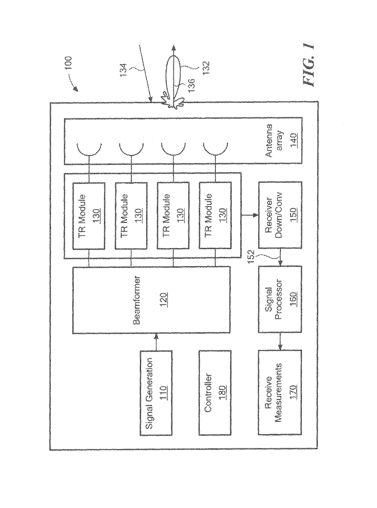
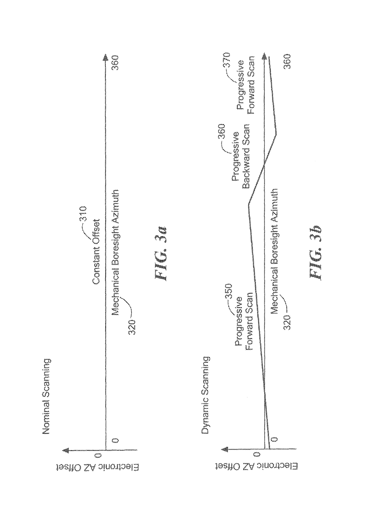
[0031]According to an embodiment, an electronic azimuth beam steering is determined that will vary the net azimuth beam scan rate (sum of mechanical plus electronic) with slow down at azimuths where extra dwell time is used, e.g., to compensate for heavy rain loss, and speed up where reduced dwell time is allowed, e.g., by available margin in light rain sectors. Rain loss is determined by processing extended target detections from weather survey dwells. Thus, an electronic azimuth scanning strategy is provided for rotating active electronically steered phased...


PUM


Abstract

Embodiments for providing dynamic azimuth scanning are generally described herein. In some embodiments, weather survey measurements are performed to estimate environmental losses as a function of azimuth angles. Gain improvements are determined based on the amount of energy increase used at different azimuth angles derived from the azimuth loss survey measurements. A gain profile is generated based on the determined gain improvements. An azimuth offset profile is derived using the gain profile to define azimuth angles where progressive scan back is used in the area of environmental losses to provide additional power and to define azimuth angles where progressive scan forward is used in regions of low loss. Dynamic electronic azimuth beam steering provides a near-constant average target detection range as a function of azimuth in the presence of non-uniform loss.

Description

BACKGROUND[0001]Rotating three dimensional surveillance radars normally use a template or fan of search beams which cover the elevation extent of the surveillance volume and are steered to the mechanical azimuth of the antenna. This approach provides a uniform distribution of radar energy and probability of detection as a function of azimuth when presented with azimuthally symmetric environmental conditions. If however, the environmental conditions are not azimuthally symmetric, such as in the presence of locally strong clutter or weather conditions at particular azimuth angles, then this scanning approach results in locally reduced probability of detection and target range at those angles. Rain interference in the microwave region can be of such intensity that the tracking of an aircraft, or for that matter any object, becomes difficult, if not impossible.[0002]To compensate for these types of conditions, low frequency bands have been used because precipitation and cloud losses are...

Claims


Application Information

Patent Timeline
IPC IPC(8): H01Q3/26
CPCH01Q3/26G01S7/03G01S13/426G01S2013/0245Y02A90/10
Inventor POWERS, PATRICK J.LANZKRON, PAUL J.
Owner RAYTHEON CO
Features
  • R&D
  • Intellectual Property
  • Life Sciences
  • Materials
  • Tech Scout
  • Unparalleled Data Quality
  • Higher Quality Content
  • 60% Fewer Hallucinations
Learn More