
Die cushion-cum-slide cushion device and method of controlling the same

a cushion device and cushion technology, applied in the field of die cushioncumslide cushion device and a control method, can solve the problems of high cost, inability to operate in the most part of one pressing cycle period, and inability to reduce the pressure, so as to improve the delay of rising response

Active Publication Date: 2019-05-14
AIDA ENG LTD
View PDF10 Cites 2 Cited by
  • Summary
  • Abstract
  • Description
  • Claims
  • Application Information

AI Technical Summary

Benefits of technology

The invention is a slide cushion device that uses a servo motor to control the force applied to the upper cushion pad during a pressing cycle. The device is more energy efficient than previous hydraulic pump / motor / servo motor combinations and uses a proportional valve to reduce oil flow and pressure loss. In addition, the servo motor is controlled to improve the delay of the rising response of the slide cushion force. This results in a more effective and efficient device for cushioning and controlling the movement of objects.

Problems solved by technology

Thus, a servo motor of a conventional die cushion device does not operate in most part of the one pressing cycle period.
While the servo die cushion device has high functionality related to applying die cushion force (has an advantage), it has an aspect of being expensive (a disadvantage).
In addition, the proportional valve provided in parallel with the hydraulic pump / motor (and a servo motor) reduces an oil flow discharged from a hydraulic cylinder, and then the proportional valve causes pressure loss because the oil flow serves as a part of die cushion force.
As a result, the die cushion device has energy efficiency less than that of a die cushion device having only the hydraulic pump / motor (and a servo motor).

Method used


Image

  • Die cushion-cum-slide cushion device and method of controlling the same
  • Die cushion-cum-slide cushion device and method of controlling the same
  • Die cushion-cum-slide cushion device and method of controlling the same

Examples


Embodiment Construction

[0043]With reference to accompanying drawings, preferable embodiments of a die cushion-cum-slide cushion device in accordance with the present invention will be described in detail below.

(Configuration of Die Cushion-Cum-Slide Cushion Device)

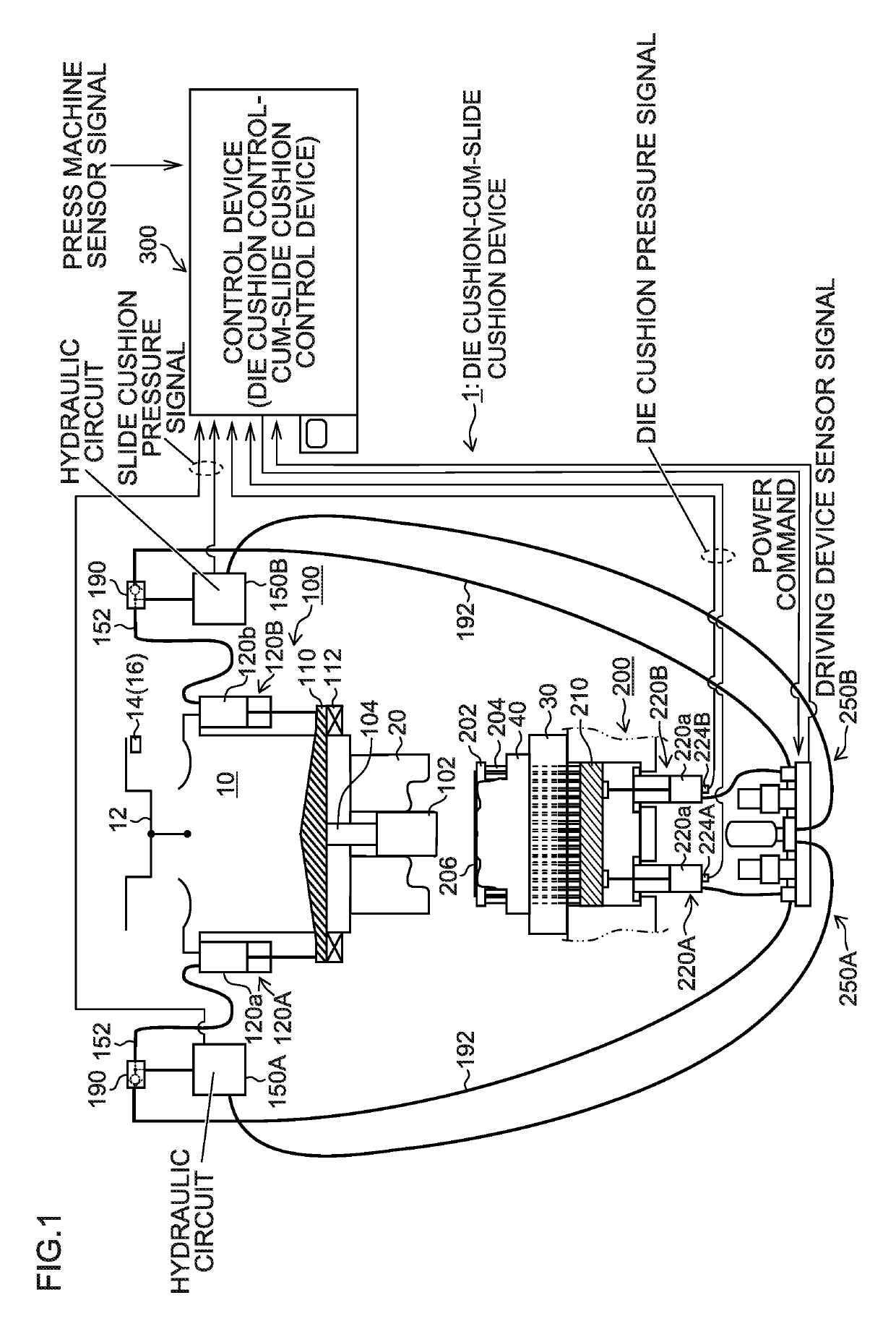
[0044]FIG. 1 is a constitution diagram illustrating an embodiment of the die cushion-cum-slide cushion device in accordance with the present invention.

[0045]In FIG. 1, a press machine, which uses a die cushion-cum-slide cushion device 1 in accordance with the present invention, is a crank press provided with a slide 10 to which driving force is transmitted through a crank mechanism. The slide 10 is moved vertically in FIG. 1 by a crank mechanism including a crankshaft 12 to which rotational driving force is transmitted by a driving device. The crankshaft 12 includes a crank angle detector 14 that detects an angle of the crankshaft 12 (crank angle), and a crank angular velocity detector 16.

[0046]An upper die 20 is mounted on the slide 10, and a l...


PUM

PropertyMeasurementUnit
crank angleaaaaaaaaaa
slide cushion forceaaaaaaaaaa
pressureaaaaaaaaaa

Abstract

A die cushion-cum-slide cushion device selectively opens and closes a flow channel between a hydraulic pump / motor driven by a servo motor, and hydraulic cylinders that generate slide cushion force, or a flow channel between the hydraulic pump / motor, and hydraulic cylinders that generate die cushion force, by switching a selector valve. Before applying the slide cushion force is started, the servo motor is controlled to allow the hydraulic cylinders to generate required slide cushion force through a check valve. While the slide cushion force is applied, hydraulic circuits, each of which includes a logic valve, control pressure of the hydraulic cylinders, and hydraulic circuits, each of which includes the servo motor, control die cushion pressure of the hydraulic cylinders.

Description

CROSS-REFERENCE TO RELATED APPLICATIONS[0001]This Application claims priority to Japanese Patent Application No. 2015-138928 filed Jul. 10, 2015, the subject matter of which is incorporated herein by reference in entirety.BACKGROUND OF THE INVENTION[0002]Field of the Invention[0003]The present invention relates to a die cushion-cum-slide cushion device and a method of controlling the same, and more particularly to a technique of allowing a servo motor used for the die cushion device to be also used for the slide cushion device.[0004]Description of the Related Art[0005]Heretofore, a servo die cushion device using a servo motor has been described in Patent Literature 1 (Japanese Patent Application Laid-Open No. JP 2006-315074 A) and Patent Literature 2 (International Publication No, WO 2010 / 058710 A1).[0006]The die cushion device described in Patent Literature 1 is configured to allow a lower chamber (pressure generating chamber) of a hydraulic cylinder supporting a cushion pad to be ...

Claims


Application Information

Patent Timeline
Patent Type & Authority Patents(United States)
IPC IPC(8): B21D24/02B21D24/14B21D24/12B30B15/06
CPCB21D24/02B21D24/14B21D24/12B30B15/061
Inventor KOHNO, YASUYUKI
Owner AIDA ENG LTD
Learn More