Method for forming perovskite solar cell with printable carbon electrode

Inactive Publication Date: 2019-05-14
NANO & ADVANCED MATERIALS INST
View PDF5 Cites 10 Cited by
  • Summary
  • Abstract
  • Description
  • Claims
  • Application Information

AI Technical Summary

Benefits of technology

[0014]Optionally, the carbon ink further comprises metal particles dispersed

Problems solved by technology

One problem is that in forming a top electrode on top of a perovskite layer of the solar cell, the top electrode is usually fabricated by a vacuum-based process, which is energy-consuming and costly.
However, this method involves high temperature annealing at 400-500° C. Th

Method used


Image

  • Method for forming perovskite solar cell with printable carbon electrode
  • Method for forming perovskite solar cell with printable carbon electrode
  • Method for forming perovskite solar cell with printable carbon electrode

Examples


Embodiment Construction

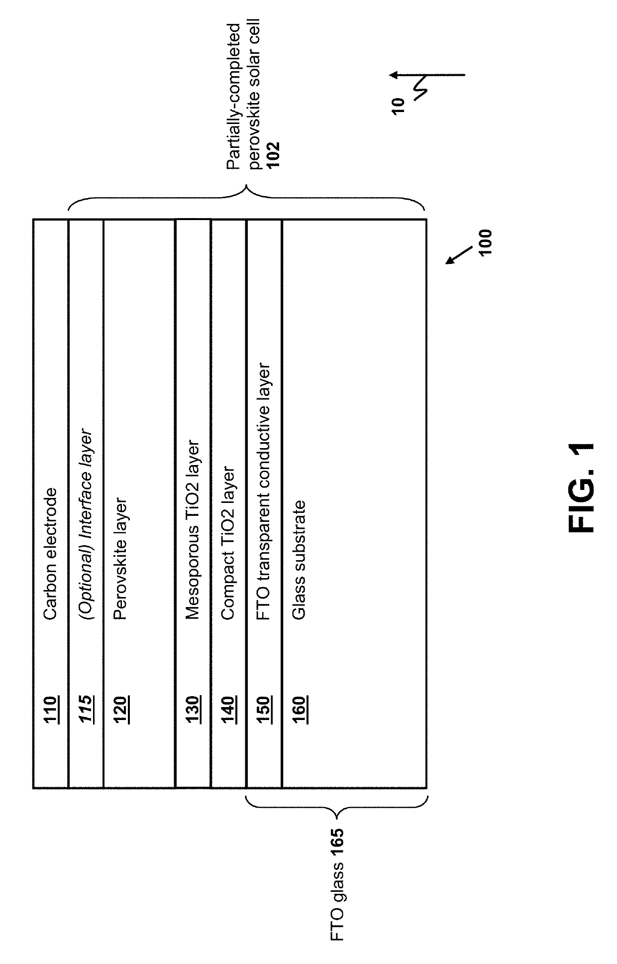
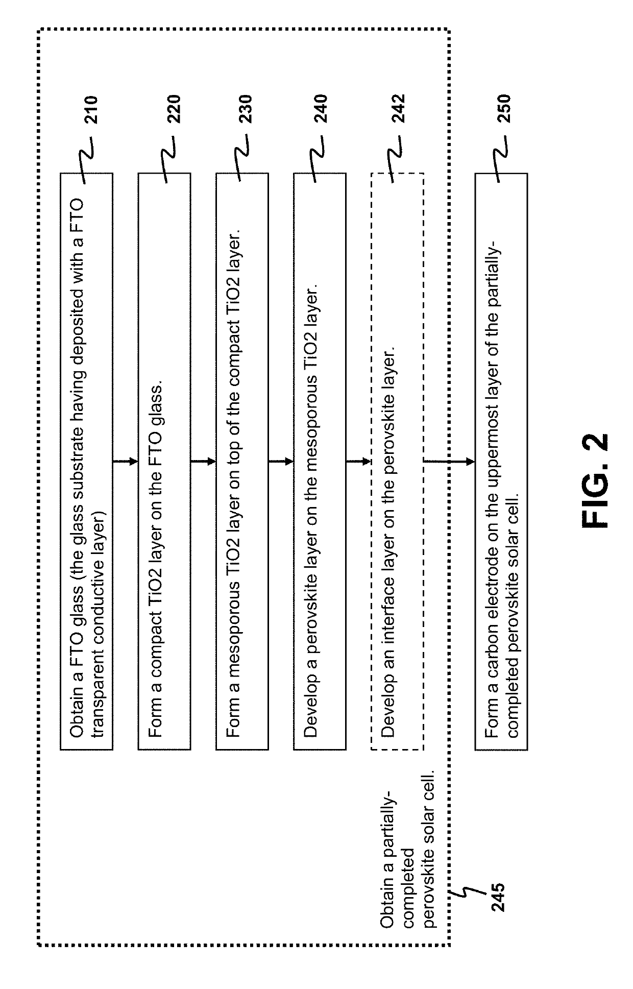
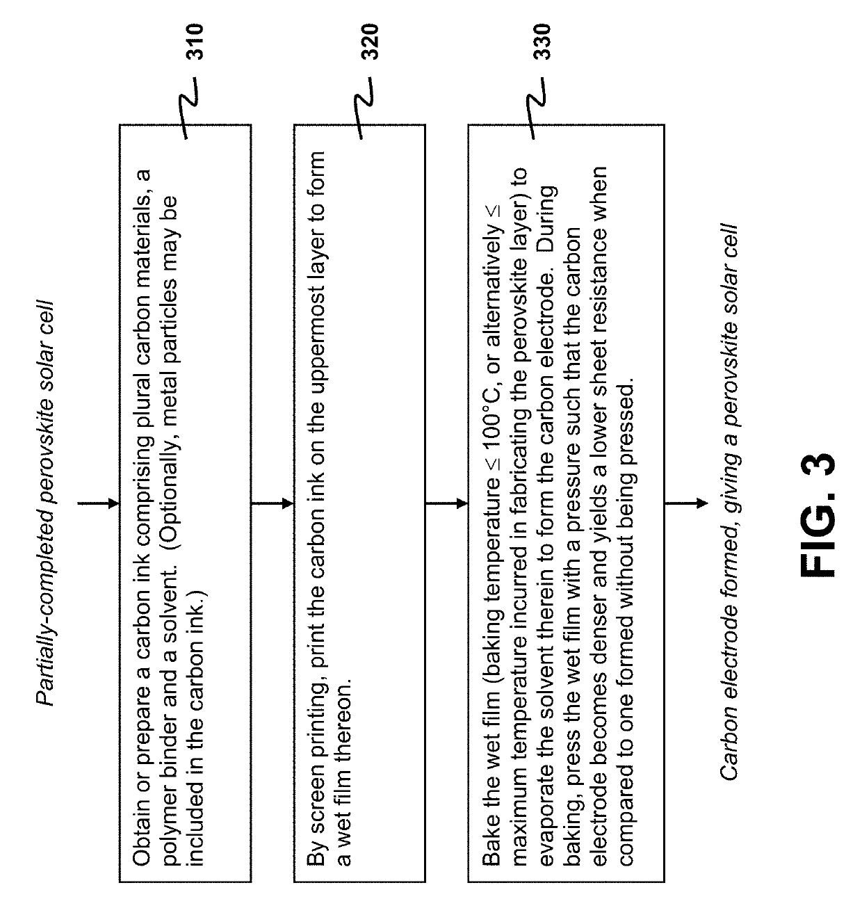
[0021]The present invention provides a technique for fabricating a PSC with a printable carbon electrode. Particularly, the present invention details a method for forming the carbon electrode on a perovskite layer or an interface layer of the solar cell without using high-temperature annealing at a temperature of 400-500° C. The interface layer is an optional layer above the perovskite layer for improving the PCE. Specifically, an embodiment of the present invention allows a baking temperature of only 100° C. or lower. Furthermore, the carbon electrode is deposited onto the perovskite layer or the interface layer via printing a conductive carbon ink on the perovskite layer or the interface layer. The use of both printing and low-temperature treatment keeps a low manufacturing cost. Furthermore, the disclosed method is developed with another major objective of pushing up the PCE, through an advantageous use of a hot press treatment in forming the carbon electrode.

[0022]The focus of t...


PUM

PropertyMeasurementUnit
Temperatureaaaaaaaaaa
Fractionaaaaaaaaaa

Abstract

To fabricate a perovskite solar cell (PSC), a printable carbon electrode is formed on an uppermost layer, either a perovskite layer or an interface layer thereon, of a partially-completed PSC. A carbon ink is first prepared by dispersing carbon materials in a mixture of a polymer binder and a solvent. Then the carbon ink is screen-printed on the uppermost layer to form a wet film thereon. The wet film is baked with a baking temperature not exceeding 100° C. to evaporate the solvent to form the carbon electrode. Advantageously, the wet film is pressed with a pressure during baking such that the carbon electrode becomes denser and yields a lower sheet resistance when compared to one formed without being pressed. Preferably the pressure is at least 16,000 Pa. Experimental results show that the percentage reduction of sheet resistance can reach 40%.

Description

FIELD OF THE INVENTION[0001]The present invention relates to a method for forming a perovskite solar cell (PSC) with a printable carbon electrode on a perovskite layer.BACKGROUND[0002]A PSC has a high efficiency in power conversion and a potential to achieve a low production cost, thus making the PSC a promising candidate as an energy harvester for sustainable energy source. Recent efforts of improving the PSC for commercialization include improving the power conversion efficiency (PCE), the scalability and manufacturability of the process as well. One problem is that in forming a top electrode on top of a perovskite layer of the solar cell, the top electrode is usually fabricated by a vacuum-based process, which is energy-consuming and costly. Developing printable electrode materials for the PSC using a solution-based process is therefore highly desirable.[0003]There have been attempts to develop a carbon electrode formed by a conductive ink comprising, for example, metal oxide and...

Claims


Application Information

Patent Timeline
IPC IPC(8): H01L51/50C09D11/037C09D7/40C09D11/102H01L51/42H01G9/20C09D11/52H01G9/00H01L51/00C08K3/04
CPCH01G9/2022H01G9/2009H01G9/2031H01L51/4226H01L51/0022H01L51/0048C09D11/102C09D7/67C09D7/68C09D11/037C09D11/52H01G9/0029H01L51/0077C08K3/04C08K3/041C08K3/042C08K3/046C08K2201/005C08K2201/001Y02E10/542Y02E10/549Y02P70/50H10K71/611H10K71/40H10K85/20H10K85/30H10K30/151H10K30/81H10K2102/102H10K30/50H10K85/50H10K85/221
Inventor LI, QIANCAI, CHAOYANG, QINGDANLI, JIAHO, PAUL KWOK KEUNG
Owner NANO & ADVANCED MATERIALS INST
Why Eureka
Try Eureka