
Method for manufacturing female terminal and female terminal
a technology of terminals and female terminals, applied in the field of female terminals, can solve the problems of reducing the strength of resilient contact pieces that are thinned by press-working, and achieve the effect of suppressing the strength of resilient contact pieces
- Summary
- Abstract
- Description
- Claims
- Application Information
AI Technical Summary
Benefits of technology
Problems solved by technology
Method used
Image

Examples
first embodiment
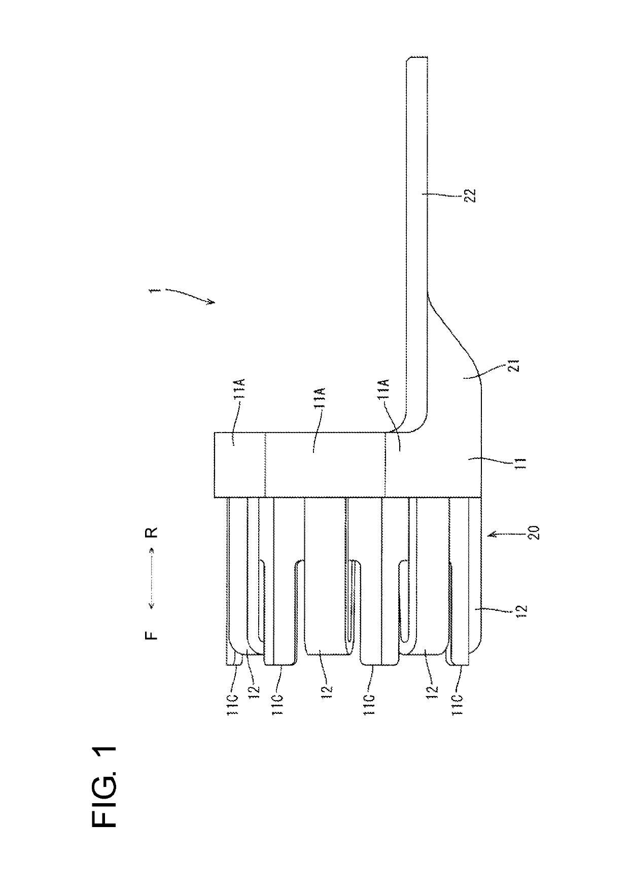
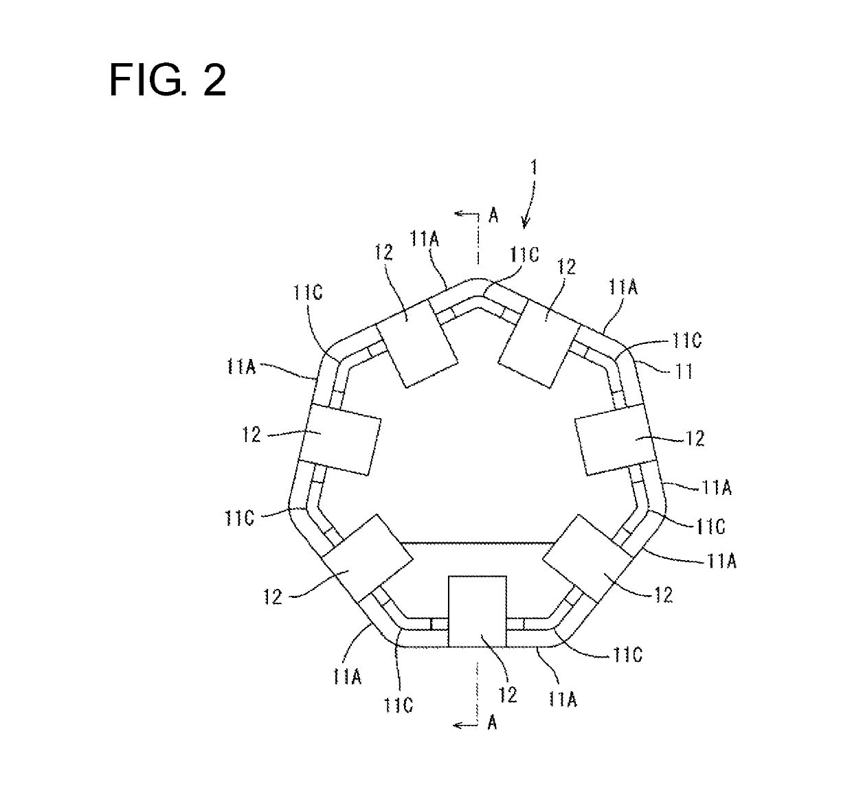
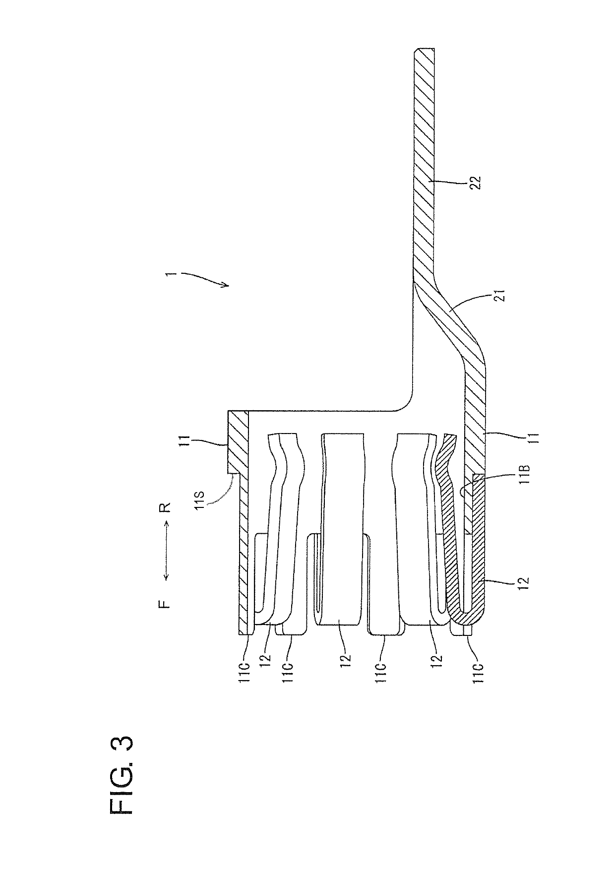
[0022]A first embodiment is described with reference to FIGS. 1 to 3. In the following description, a front-rear direction is based on a front-rear direction shown in FIG. 1.
[0023]A multi-contact terminal 1 as a female terminal according to the first embodiment is illustrated in FIGS. 1 and 2. The multi-contact terminal 1 is a large current terminal used, for example, in a power supply line of an electric vehicle, hybrid vehicle or the like.
[0024]The multi-contact terminal 1 includes a polygonal tube 11 having a heptagonal tube shape and seven leaf springs 12. An unillustrated male terminal in the form of a round bar is inserted into the tube 11 from the front. When the male terminal is inserted, the seven leaf springs 12 resiliently contact the outer peripheral surface of the male terminal inside the tube 11 and the male terminal and the multi-contact terminal 1 are connected electrically. The tube 11 is an example of a tubular portion. The leaf spring 12 is an example of a resilie...
second embodiment
[0049]A second embodiment is described with reference to FIGS. 4 and 5.
[0050]In a multi-contact terminal 201 according to the second embodiment, leaf springs 12 are joined to a polygonal tube 11 not by laser welding, but by caulking.
[0051]As shown in FIG. 4, a thin portion 11B of a metal plate according to the second embodiment is formed with circular through holes 11D penetrating in a plate thickness direction. As shown in FIG. 4, metal members in the form of long plates to be formed as the leaf springs 12 are pressed circularly at positions corresponding to the through holes 11D from an outer surface by a press apparatus in a joining step according to the second embodiment (see FIG. 5).
[0052]As shown in FIG. 4, when the metal members are pressed by the press apparatus, materials of the metal members enter the through holes 11D of the thin portion 11B and the thin portion 11B is caulked from inner sides of the through holes 1D by the materials that have entered. In this way, the me...
PUM
 Abstract
Description
Claims
Application Information