Floating wind turbine with a floating foundation, and method for installation of such a wind turbine

a technology of wind turbines and foundations, applied in the direction of floating buildings, anchors, renewable energy products, etc., can solve the problems of long downtime, high labour expenditure for manufacturing frames, complex construction, etc., and achieve the effect of simple method, low labor expenditure, and simple structur

Active Publication Date: 2019-06-04
AERODYN ENG GMBH
View PDF20 Cites 5 Cited by
  • Summary
  • Abstract
  • Description
  • Claims
  • Application Information

AI Technical Summary

Benefits of technology

[0011]A first objective of the invention is therefore so to improve the structure of the last two mentioned floating wind turbines relative to their foundation that a compact and stable floating wind turbine is created that is of simple structure, can be produced with little labour outlay and on top on this is suitable in terms of its basic construction for waters both with a low and also with a great depth. The further object of the invention is to create a simple method that can be carried out quickly for installing such wind turbines.
[0012]The basic idea of the invention is, on the one hand, to design the geometry in the horizontal and in the vertical extent of the system such that the loads occurring on the rotor and / or on the energy conversion unit are dissipated, as directly as possible, into the foundation without the bending or torsional moments occurring on the tower. By intercepting the tensile and compressive forces acting on the tower of the wind turbine and the minimization, associated therewith, of the bending moment acting on the tower, it is possible, to reduce the horizontal and vertical extent of the foundation such that the wind turbine designed according to the invention is suitable both for large and also for small water depths.

Problems solved by technology

However, a disadvantage of this design is the complexity of the construction and the high labour expenditure for manufacturing the frame.
However, the disadvantage here is the catamaran-like design of the foundation and the arrangement of the tower on a web connecting the buoyancy bodies, so that the loads occurring at the rotor and / or at the energy conversion unit are dissipated into the foundation in a rather one-sided manner and the floating wind turbine tends to list.
In addition to the construction of offshore wind turbines themselves, it is also their installation that represents a particular challenge.
The disadvantage of this anchoring is, however, the high effort for decoupling the mooring lines that anchor the offshore wind turbine and also the electrical connection to the submarine cable so that in the case of maintenance or repair, if the system is to be towed again into the harbour, long downtimes have to be expected despite assumed favourable weather conditions.

Method used


Image

  • Floating wind turbine with a floating foundation, and method for installation of such a wind turbine
  • Floating wind turbine with a floating foundation, and method for installation of such a wind turbine
  • Floating wind turbine with a floating foundation, and method for installation of such a wind turbine

Examples


Embodiment Construction

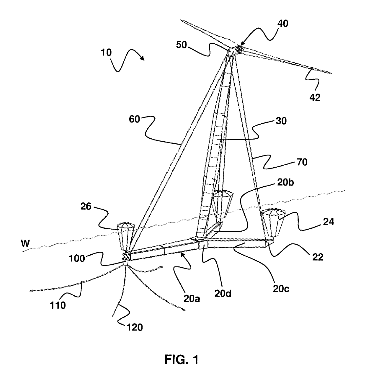
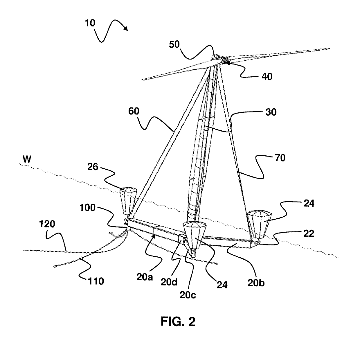
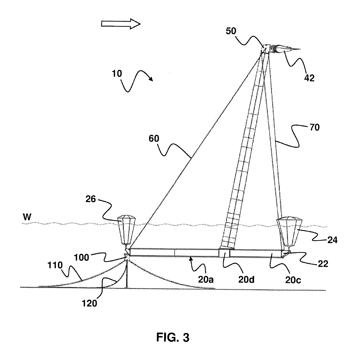
[0050]FIG. 1 shows a perspective view of a particularly preferably designed floating offshore wind turbine 10 at the site of a pre-installed floating body 100 for anchoring the floating wind turbine 10 on the sea bed obliquely from upwind, whereas FIG. 2 illustrates a perspective view of this wind turbine obliquely from downwind.

[0051]The floating wind turbine 10 exhibits a floating foundation 20 that—as will be detailed subsequently—is of three-leg design, the leg 20a connected to the floating body 100 being longer than the two other legs 20b, 20c. During operation of the wind turbine 10, the floating foundation 20 is arranged completely below the water line W. The legs 20a, 20b, 20c are in each case connected at their free ends to a buoyancy body 24, 26, the buoyancy bodies 24 arranged at the short legs 20b, 20c being designed such that they exhibit a larger buoyancy than the buoyancy body 26 arranged at the long leg 20a. The buoyancy bodies 24, 26 are in each case illustrated hav...


PUM


Abstract

A floating downwind turbine comprising: a floating foundation; a tower which is rotationally fixed on the floating foundation; an energy conversion unit which is mounted on the tower, comprises a rotor and is rotationally fixedly connected to the tower; and at least one tensioning element which connects the tower or the energy conversion unit to the foundation in the upwind direction, the foundation having three legs, one leg of which is longer than the other two legs, the legs being interconnected in a Y shape and the tower, being arranged on the foundation in the connecting region of the legs, and the longest leg extending in the upwind direction and being connected to the tower or to the energy conversion unit by the tensioning element.

Description

CROSS REFERENCE TO RELATED APPLICATIONS[0001]This application represents the U.S. National Stage of International Application No. PCT / DE2015 / 100225, filed 5 Jun. 2015 which claims priority from and the benefit of German Patent Application No. 10 2014 109 212.0 filed on 1 Jul. 2014. The entire contents of these applications are incorporated herein by reference.BACKGROUND OF THE PRESENT INVENTION[0002]The invention relates to a floating wind turbine comprising a floating foundation, a tower arranged on the floating foundation, and an energy conversion unit which is mounted on the tower and comprises a rotor, the wind turbine being designed as a downwind turbine, the floating foundation being rotatable anchored, and the tower being rotationally fixedly connected to the floating foundation on the one hand and the energy conversion unit on the other hand.[0003]Floating wind turbines for large water depths are for example known from EP 2 271 547 B1. Such structures consists in particular ...

Claims


Application Information

Patent Timeline
Patent Type & Authority Patents(United States)
IPC IPC(8): B63B35/44B63B21/20B63B21/26F03D1/06B63B1/12B63B21/50F03D13/20F03D13/25F03D13/10
CPCB63B35/44B63B21/20B63B21/26B63B21/50F03D1/0675F03D13/10F03D13/22F03D13/25B63B1/125Y02P70/523B63B2001/128B63B2021/203B63B2035/446F05B2230/60F05B2240/93F05B2240/95Y02E10/721Y02E10/727Y02E10/72Y02P70/50
Inventor SIEGFRIEDSEN, SONKE
Owner AERODYN ENG GMBH
Why Eureka
Try Eureka