Insect trap

a technology of insect traps and traps, which is applied in the field of insect traps, can solve the problems of decreasing the intake of fodder and the egg laying rate in the chicken industry, and achieve the effects of reducing the foul odor generated during the processing of chicken excreta, accelerating the biodegradation of fragments, and increasing the iron content of manur

Active Publication Date: 2019-06-11
SHIKOKU CAGE CO LTD
View PDF25 Cites 5 Cited by
  • Summary
  • Abstract
  • Description
  • Claims
  • Application Information

AI Technical Summary

Benefits of technology

[0010]When such a mixer is used, the insect trap can be dropped into the mixer and crushed into fragments by the mixer; at the same time, the fragments can be mixed with chicken excreta to accelerate biodegradation of the fragments. Since the exothermic powder included in the insect trap contains iron powder, iron content of the manure increases when the fragments of the insect trap are mixed with chicken excreta, compared with when manure is made of chicken excreta alone. Used insect traps can thus be utilized to produce manure that is suitable for application on agricultural crops requiring iron. Furthermore, since iron absorbs causative substances of foul odor such as ammonia, hydrogen sulfide, and trimethylamine, foul odor generated during processing of chicken excreta can be reduced.

Problems solved by technology

Due to anemia and stress caused by hematophagous behavior of these insect pests, there are problems of decreasing intake of fodder and decreasing egg laying rate in the chicken industry.

Method used


Image

  • Insect trap
  • Insect trap
  • Insect trap

Examples


first embodiment

1. First Embodiment

[0019][1-1. Configuration]

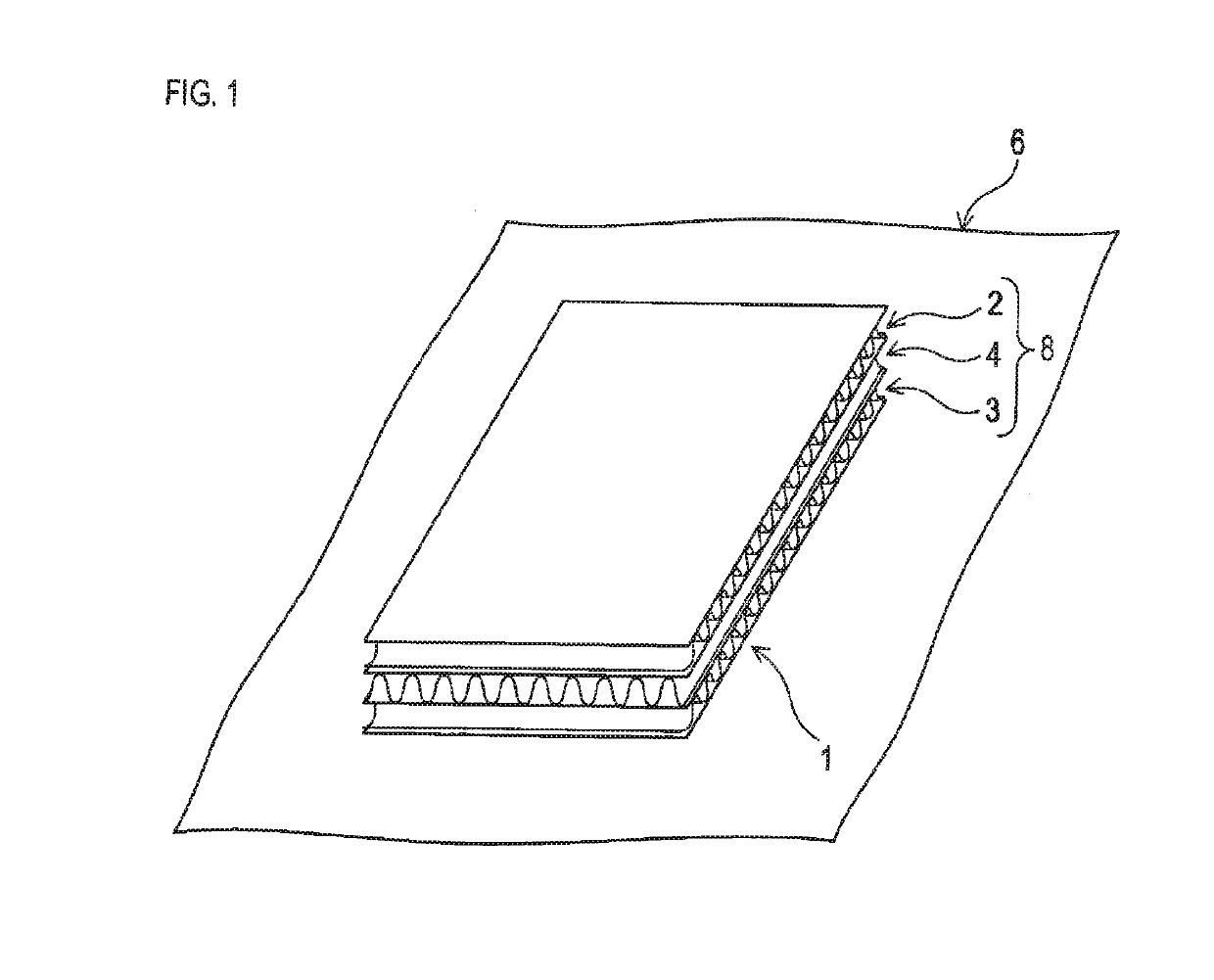
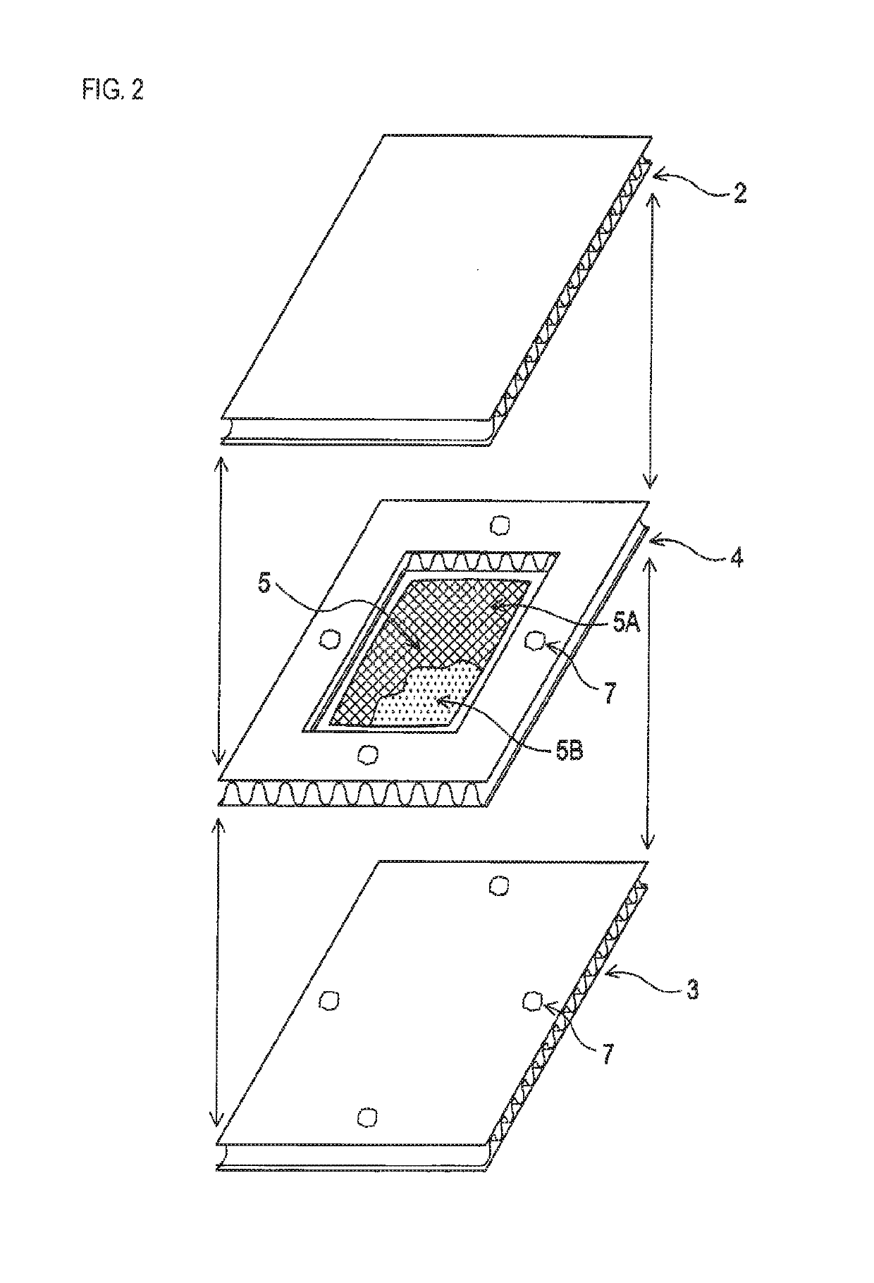
[0020]An insect trap 1 shown in FIG. 1 and FIG. 2 comprises a layered body 8, and an exothermic body 5 arranged inside the layered body 8. The insect trap 1 is enclosed in an airtight outer bag 6.

[0021]The layered body 8 has a layered structure comprising three rectangle cardboard sheets 2, 3, and 4 (which correspond to one example of plate-like elements in the present specification). The cardboard sheets 2, 3, and 4 are those typically known and configured with a corrugated core material, and two liners that are respectively bonded to both sides of the core material to place the core interposed between the two liners. The cardboard sheets 2, 3, and 4 may be those configured with a core material, and one liner (so-called single-face cardboards).

[0022]The cardboard sheets 2, 3, and 4 selected for use are high in biodegradability. Specifically, the cardboard sheets 2, 3, and 4 made from 100 percent recycled paper are used. Use of such cardb...

second embodiment

2. Second Embodiment

[0050]Basic configurations of the second embodiment are the same as those of the first embodiment. Therefore, explanation is omitted with respect to common configurations, but is focused on differences. In the second embodiment, the same reference numerals as those of the first embodiment represent the same configurations, and therefore refer to the preceding explanations.

[0051][2-1. Configuration]

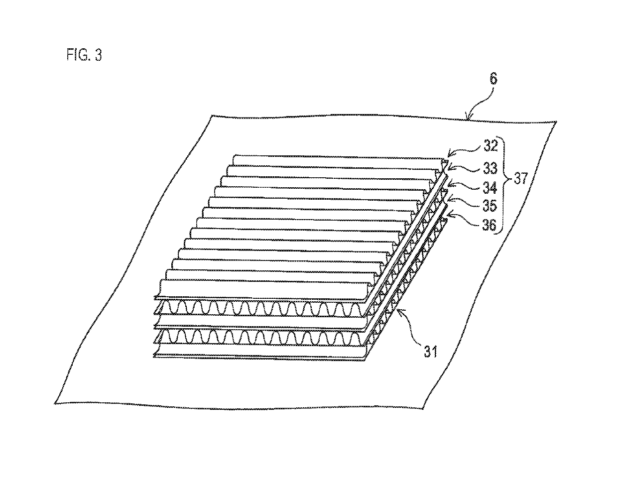
[0052]The insect trap 31 shown in FIG. 3 and FIG. 4 comprises the layered body 37, and an exothermic body 5 arranged inside the layered body 37.

[0053]The layered body 37 has a layered structure comprising five square cardboard sheets 32, 33, 34, 35, and 36.

[0054]Among the five cardboard sheets 32, 33, 34, 35, and 36, the cardboard sheets 33, 34, and 35, which are interposed between two cardboard sheets 32, and 36 situated as the most superficial layers of the layered body, each have their central area cut out to form a square opening. A housing space to house the exothe...


PUM


Abstract

An insect trap includes an exothermic body, and a layered body. The exothermic body is configured to include exothermic powder enclosed in an inner bag that is air permeable; the exothermic powder contains iron powder that releases heat when oxidized. The layered body is configured with layers of plate-like elements and includes gaps as a pathway of entry for an insect pest. A housing space to house the exothermic body is arranged inside the layered body. The layered body and the inner bag are made of a biodegradable raw material.

Description

CROSS-REFERENCE TO RELATED APPLICATION[0001]This Application is a 371 National Stage Application of International Application No. PCT / JP2015 / 079361, filed Oct. 16, 2015, published as WO 2016 / 088458 A1, on Jun. 9, 2016, not in English, which is based on and claims the benefit of Japanese Patent Application No. 2014-261226, filed on Dec. 5, 2014 with the Japan Patent Office, the contents of which are hereby incorporated by reference in their entireties.TECHNICAL FIELD[0002]The present disclosure relates to an insect trap.BACKGROUND ART[0003]Mites such as red mites and northern fowl mites are insect pests that feed on blood of chickens, for example. Due to anemia and stress caused by hematophagous behavior of these insect pests, there are problems of decreasing intake of fodder and decreasing egg laying rate in the chicken industry. To cope with these problems, high-temperature steam is sprayed inside chicken houses, or, agents such as insecticides are dispersed. Patent Document 1 disc...

Claims


Application Information

Patent Timeline
Patent Type & Authority Patents(United States)
IPC IPC(8): A01M1/10A01M1/02F24V30/00A01M1/20A01N59/14A01N27/00A01N25/08
CPCA01M1/103A01M1/023A01M1/10F24V30/00A01N25/08A01N27/00A01N59/14A01M1/2011A01M2200/011
Inventor IKAWA, SHIGEKI
Owner SHIKOKU CAGE CO LTD
Why Eureka
Try Eureka