

Circuit board and method for manufacturing the same
a technology of circuit boards and materials, applied in the field of circuit boards, can solve the problems of not being able to endure high temperature production processes, almost all of these materials are not biodegradable, and the manufacturing of these materials may pollute the environment, so as to enhance the stability of the circuit board
- Summary
- Abstract
- Description
- Claims
- Application Information
AI Technical Summary
Benefits of technology
Problems solved by technology
Method used
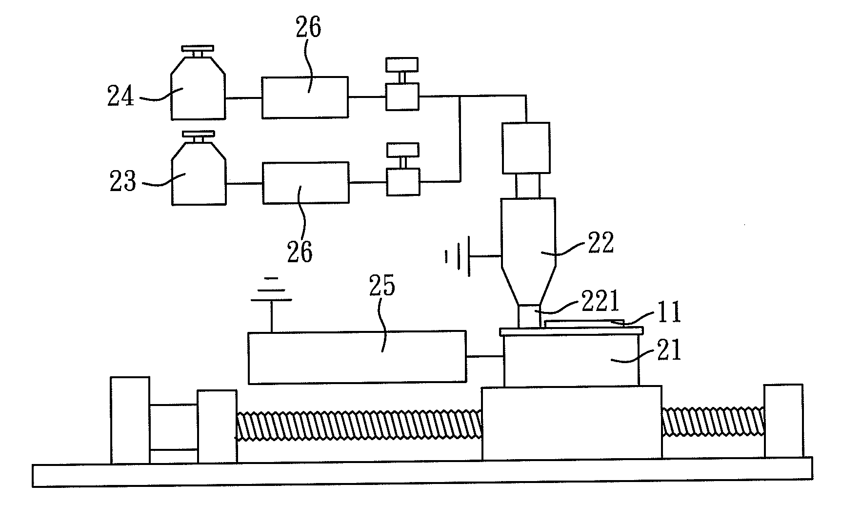
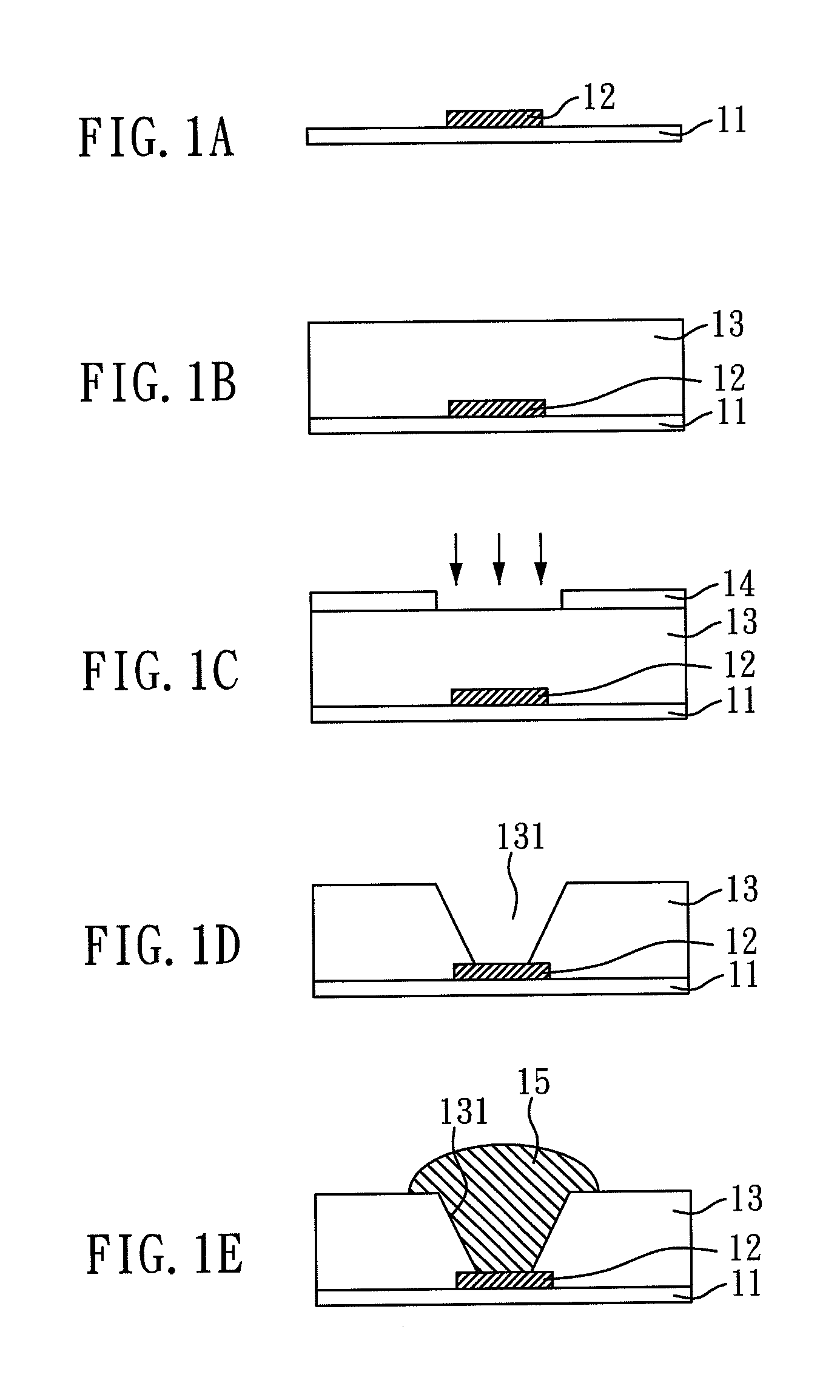
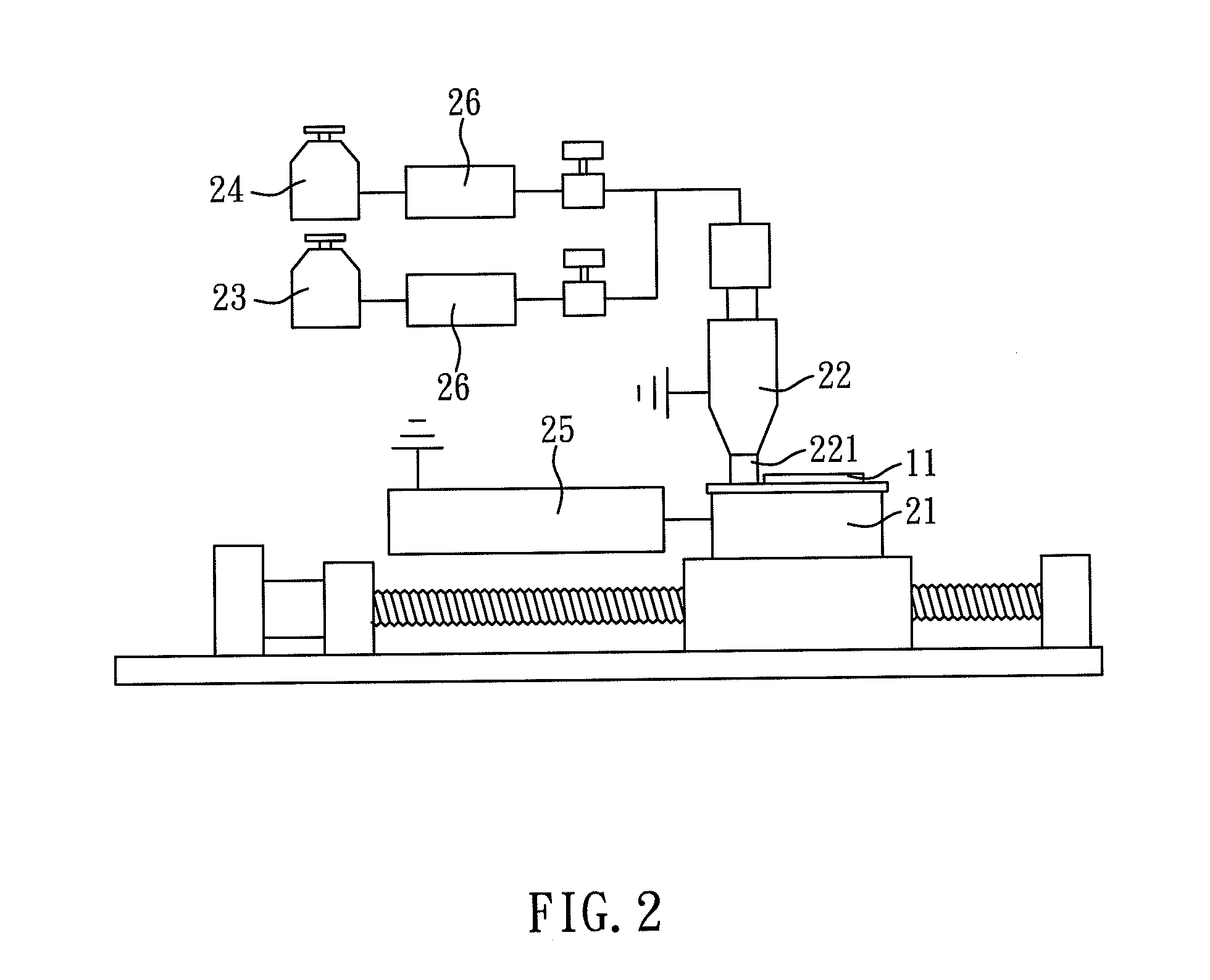
Image

Examples
embodiment 1
Connection Structure of Circuit Board Using Silk Fibroin as Dielectric Material
Preparation of a Silk Solution
[0039]First, 10 wt % of an aqueous solution of Na2CO3 was provided and heated. When the solution was boiling, natural silk was added thereto, and the solution was kept boiling to remove sericin. Then, the silk without sericin was washed by deionized water to remove the alkali salt adhered on the silk. After a drying process, refined silk, i.e. fibroin, was obtained.
[0040]Next, the refined silk was added into 85 wt % of phosphoric acid (H3PO4) solution (20 ml), and the resulted solution was stirred until the refined silk was dissolved. Then, the phosphoric acid solution containing the refined silk was put into a membrane (Spectra / Por 3 membrane, molecular weight cutoff=14000). The dialysis process was performed for 3 days to remove the phosphoric acid. Finally, a filter paper was used to filter out impurities, and an aqueous solution of fibroin was obtained.
Preparation of a Co...
embodiment 2
Connection Structure of Circuit Board Using Hydrolyzed Collagen as Dielectric Material
[0050]The connection structure of the circuit board and the method for manufacturing the same of the present embodiment were the same as those of Embodiment 1, except that the silk solution used in Embodiment 1 was substituted with a hydrolyzed collagen solution in the present embodiment. Hence, the material of the protein dielectric layer of the circuit board of the present embodiment is hydrolyzed collagen.
[0051]The hydrolyzed collagen used in the present embodiment was extracted from pigskin, and the process for preparing the hydrolyzed collagen solution was shown as follow.
[0052]Hydrolyzed collagen powders extracted from pigskin was obtained from Ken Le Ad Development CO., LTD. The hydrolyzed collagen powders were dissolved in de-ionized water to obtain a hydrolyzed collagen solution with a concentration of 3-4 wt %.
[0053]Here, the protein dielectric layer made from hydrolyzed collagen was also...
embodiment 3
Connection Structure of Circuit Board Using Wool Keratin as Dielectric Material
[0054]The connection structure of the circuit board and the method for manufacturing the same of the present embodiment were the same as those of Embodiment 1, except that the silk solution used in Embodiment 1 was substituted with a wool keratin solution in the present embodiment, and the etching time of the plasma treatment was 5 mins. Hence, the material of the protein dielectric layer of the circuit board of the present embodiment is wool keratin.
[0055]The wool keratin used in the present embodiment was extracted from wool, and the process for preparing the wool keratin solution was shown as follow.
[0056]First, wool was washed in water for several times to remove dust and soil on the wool. Then, the clean wool was placed into an oven for 24 hrs to dry it completely. The dried wool was dipped into a solution containing alcohol and acetone (1:1) and stirred for 12 hrs, to remove the wool oil from the wo...
PUM
| Property | Measurement | Unit |
|---|---|---|
| diameter | aaaaa | aaaaa |
| time | aaaaa | aaaaa |
| conductive | aaaaa | aaaaa |
Abstract
Description
Claims
Application Information