
Measuring transducer

a technology of measuring transducer and measuring device, which is applied in the direction of electric devices, instruments, transportation and packaging, etc., can solve the problems of not being able to produce energy meters for direct current circuits on a large scale, and achieve the effect of increasing the efficiency of measuring transducers and reducing the use of measuring

Inactive Publication Date: 2019-06-18
COMPLEO CHARGING SOLUTIONS AG
View PDF13 Cites 0 Cited by
  • Summary
  • Abstract
  • Description
  • Claims
  • Application Information

AI Technical Summary

Benefits of technology

[0015]In particular, it is proposed that the direct current measurement variable is an electrical power. The electrical power is generally determined from the electrical voltage and the electrical current in the direct current charging circuit. If the direct current measurement variable is detected at short intervals, then the alternating current actuating variable can be tracked in likewise correspondingly small intervals. Here, the alternating current actuating variable is preferably an electrical power, in particular an electrical active power. In the alternating current measuring circuit, preferably only active power is used. This can be achieved in that in the alternating current measuring circuit parasitic, capacitive or inductive loads are minimised as far as possible and in the alternating current measuring circuit only an ohmic resistance is provided. According to the subject matter, the electrical active power is preferably lower by a factor than the electrical power in the direct current charging circuit. These factors are preferably 10, 100, 1,000, 5,000 or similar.
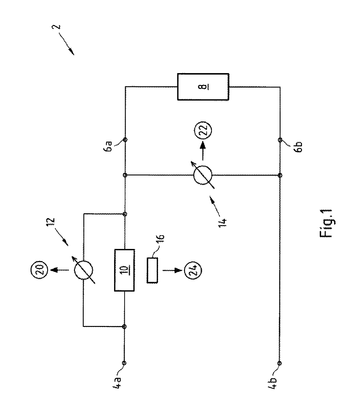
[0018]It is in particular possible to make available the current strength of the direct current charging circuit, determined on the basis of the voltage drop across the measuring resistor in a temperature-compensated manner. It is thus possible, to determine the direct current and the direct voltage in the direct current charging circuit independent of temperature in order to thus be able to determine the alternating current actuating variable independent of temperature.
[0023]The constant current source is preferably an adjustable resistor or has such an adjustable resistor. With the help of the adjustable resistor it is possible to adjust the current flow in the alternating current measuring circuit.
[0025]An active power of 46 W, for a factor of 1,000, as can be set in the transducer, can correspond to a direct current power in the direct current charging circuit of 46 KW. This means that if an electric vehicle charges at 46 KW, accordingly in the alternating current measuring circuit only 46 W of “measuring service” is used. A higher factor leads to an even lower use of “measuring service” in the alternating current measuring circuit, thereby increasing the efficiency of the measuring transducer.

Problems solved by technology

However, energy meters for direct current circuits are not produced on a large scale and are generally not authorised under the calibration regulations.

Method used


Image

  • Measuring transducer
  • Measuring transducer
  • Measuring transducer

Examples


Embodiment Construction

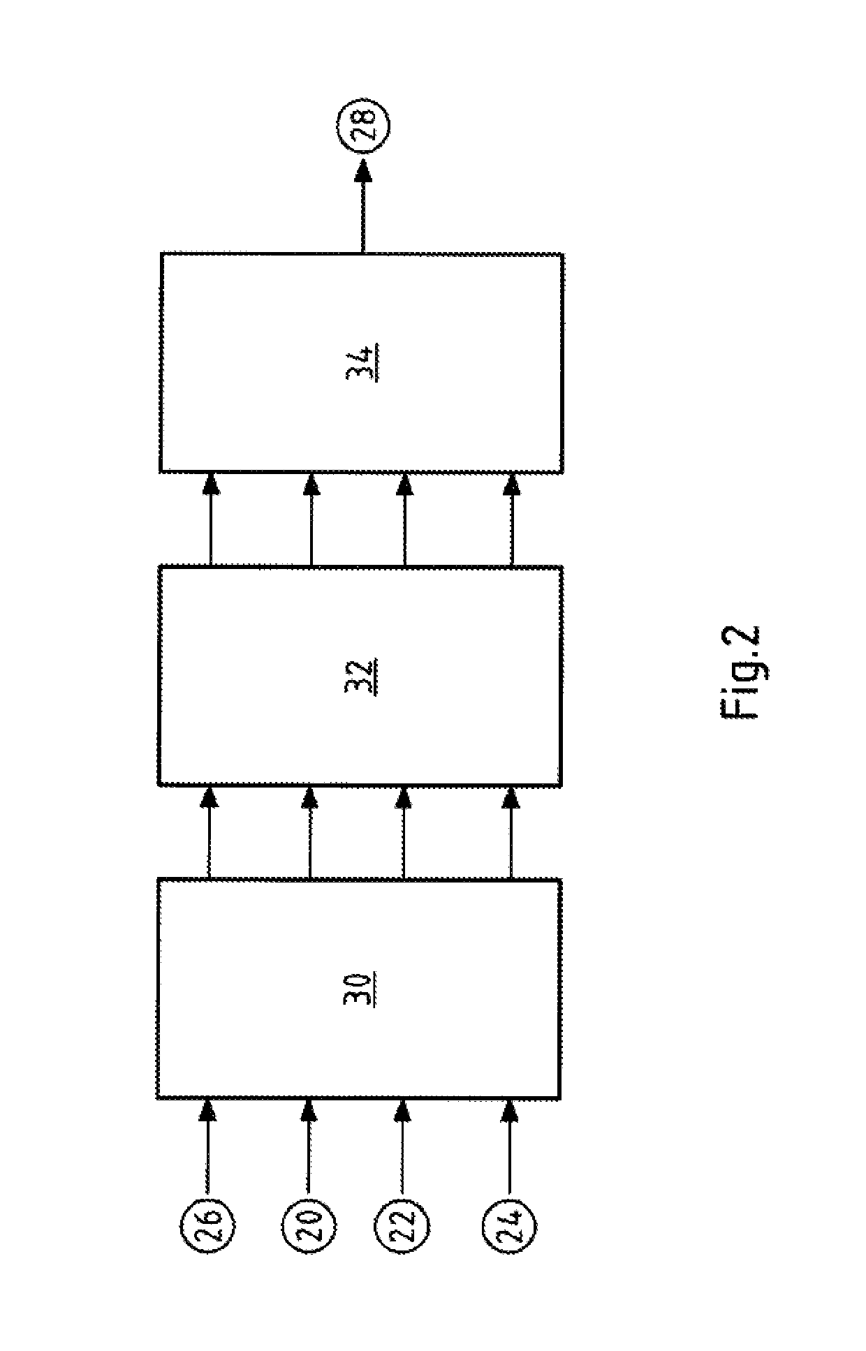
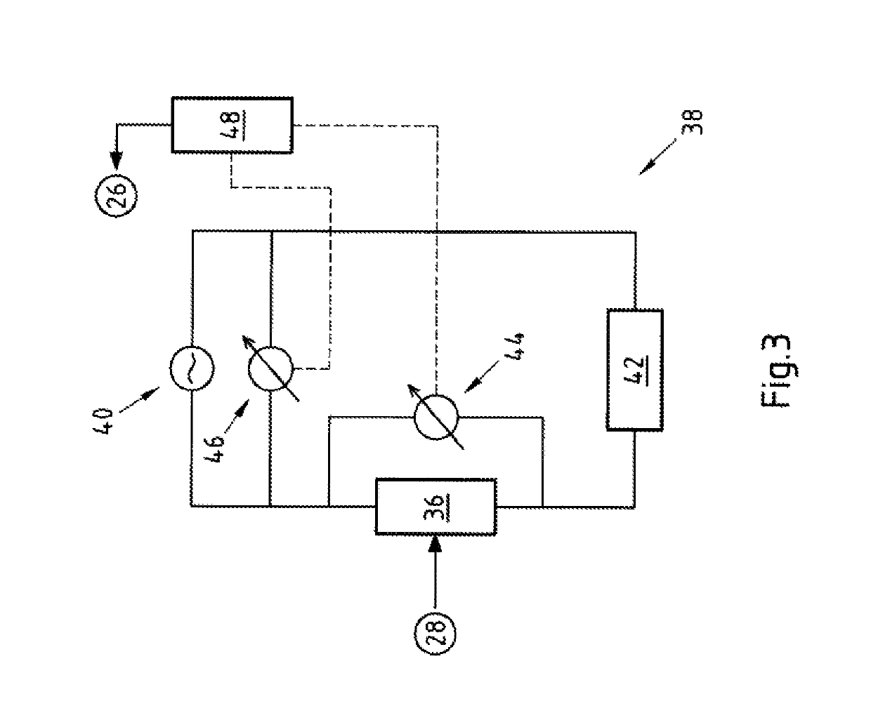
[0035]FIG. 1 shows a direct current charging circuit 2. The direct current charging circuit 2 is fed via a rectifier (not shown) with direct voltage at its connections 4a, 4b. The direct current charging circuit is generally designed for powers of more than 10 kW, preferably more than 40 kW, in particular more than 70 kW of electrical power.

[0036]Via charging contacts 6a, 6b an electric vehicle 8 can be connected to the direct current charging circuit 2. The direct current charging circuit 2 is generally installed in a charging station, which via a suitable plug contact can be connected to an electric vehicle 8. The direct current charging circuit 2 is shown, for the purposes of clarity, with just the relevant measurement devices necessary for the measuring transducer that is the subject matter. The direct current charging of an electric vehicle 8 naturally requires further technical devices which, for the sake of clarity, are not shown here, though.

[0037]In the direct current charg...


PUM


Abstract

The invention relates to a measuring transducer for charging stations of electric vehicles. In the measuring transducer, a measuring device is connected to a direct current charging circuit for detecting at least one direct current measurement variable. A transducer for converting the direct current measurement variable into an alternating current actuating variable is provided, and the measuring transducer also includes an actuating means for adjusting at least one alternating current variable in an alternating current measuring circuit as a function of the alternating current actuating variable.

Description

CROSS-REFERENCE TO RELATED PATENT APPLICATIONS[0001]This patent application is a continuation of PCT Application No. PCT / EP2016 / 075758, filed Oct. 26, 2016, which claims priority to German Application No. 10 2016 103 556.4, filed Feb. 29, 2016, the entire teachings and disclosure of which are incorporated herein by reference thereto.FIELD[0002]The subject matter relates to a measuring transducer for charging stations of electric vehicles and to a method for operating a measuring transducer.BACKGROUND[0003]The increasing use of electric charging stations for electric vehicles is presenting new challenges with regard to the measurement technology to be employed. Particular technical challenges relate to the correct billing of electrical energy obtained. Apart from the charging of electric vehicles by means of alternating current, wide use is also made of charging with direct current. However, when charging by means of direct current, the problem arises that the measurement technology ...

Claims


Application Information

Patent Timeline
Patent Type & Authority Patents(United States)
IPC IPC(8): G01R22/10B60L3/00G01R11/38
CPCB60L53/665B60L3/0046G01R11/38G01R22/10Y02T10/7005Y02T10/7072Y02T90/121Y02T90/128Y02T90/14Y02T90/163Y02T90/169Y04S30/14Y02T10/70Y02T90/12Y02T90/167Y02T90/16
Inventor RIEMENSCHNEIDER, HOLGERCATER, STEPHANWAFFNER, JURGEN
Owner COMPLEO CHARGING SOLUTIONS AG
Learn More