Exhaust gas control apparatus for internal combustion engine
a technology of exhaust gas control apparatus and internal combustion engine, which is applied in mechanical equipment, electric control, machines/engines, etc., can solve the problems of large pump loss, increased pump loss, and not immediately returned pump loss
- Summary
- Abstract
- Description
- Claims
- Application Information
AI Technical Summary
Benefits of technology
Problems solved by technology
Method used
Image

Examples
Embodiment Construction
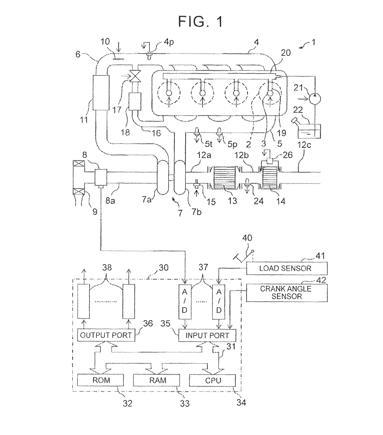
[0053]An overall view of a compression ignition-type internal combustion engine is illustrated in FIG. 1.
[0054]Referring to FIG. 1, 1 represents an engine main body, 2 represents respective combustion chambers of cylinders, 3 represents electronically controlled fuel injection valves for injecting a fuel into the respective combustion chambers 2, 4 represents an intake manifold, and 5 represents an exhaust manifold. The intake manifold 4 is connected to an outlet of a compressor 7a of an exhaust turbocharger 7 via an intake duct 6, and an inlet of the compressor 7a is connected to an air cleaner 9 via an intake air introduction pipe 8a where a suctioned air amount detector 8 is disposed. A throttle valve 10 that is driven by an actuator is disposed in the intake duct 6, and a cooling device 11 for cooling suctioned air flowing through the intake duct 6 is disposed around the intake duct 6. In the example that is illustrated in FIG. 1, engine cooling water is guided into the cooling ...
PUM
 Abstract
Description
Claims
Application Information