

Method for measuring a dental object
a technology for measuring dental objects and objects, applied in the field of measuring dental objects, can solve the problems of longer measurement time, and achieve the effect of adequate image quality and adequate roughness of the surfa
- Summary
- Abstract
- Description
- Claims
- Application Information
AI Technical Summary
Benefits of technology
Problems solved by technology
Method used
Image

Examples
Embodiment Construction
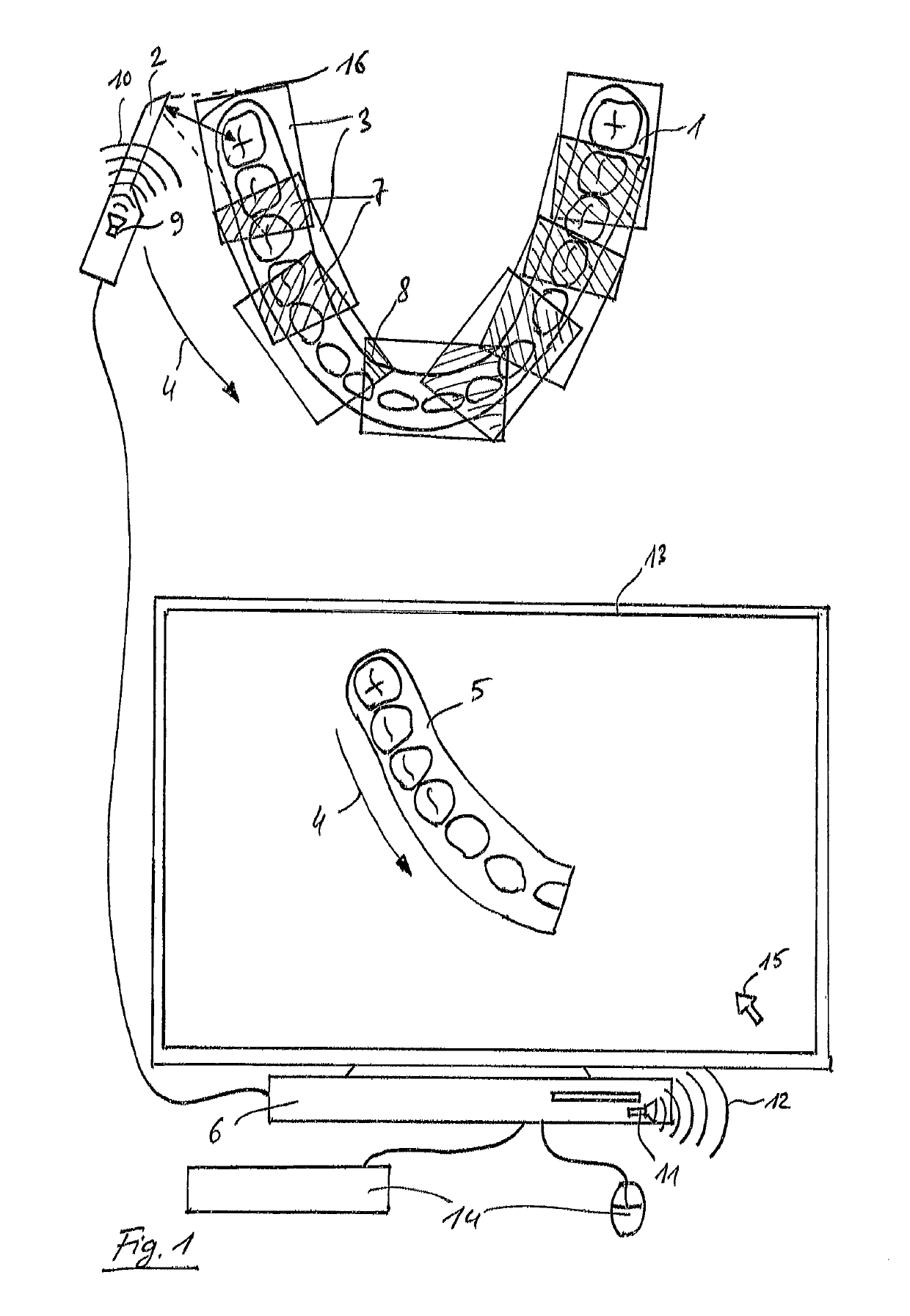
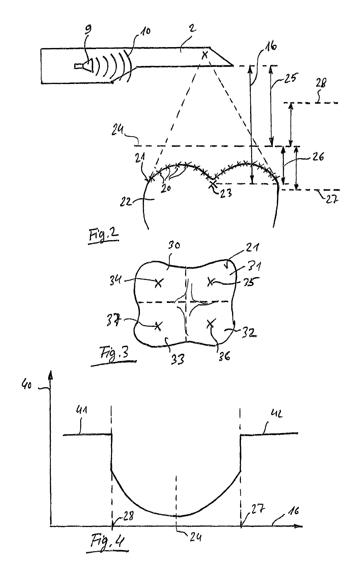
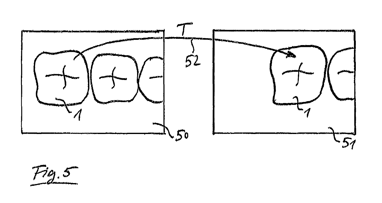
[0008]The invention relates to a method for measuring a dental object using a dental camera, wherein several optical three-dimensional images of the object are produced during the measurement. During the measurement, an acoustic sound is generated by means of a sound generator. This sound serves as a feedback for the user and imparts to the user information about the current status of a recording of the images and / or about specific recording requirements of the dental camera. During the optical measurement, several three-dimensional optical images of the dental object are recorded and then combined to form a global image. After each individual image, a check is performed automatically using a computer to ascertain whether an overlapping area between the images to be joined meets specific recording requirements for correct recording. The sound is generated by the sound generator if the recording requirements for the checked image are met. Alternatively, the sound can be generated if ...
PUM
 Abstract
Description
Claims
Application Information