Focus detection apparatus and method, and image capturing apparatus

a technology of focus detection and image capturing, which is applied in the direction of optical radiation measurement, radiation control devices, instruments, etc., can solve problems such as difficulty in appropriate correction, and achieve the effect of suppressing focus detection error and high precision focus detection

Active Publication Date: 2019-06-18
CANON KK
View PDF8 Cites 2 Cited by
  • Summary
  • Abstract
  • Description
  • Claims
  • Application Information

AI Technical Summary

Benefits of technology

[0007]The present invention has been made in consideration of the above situation, and, in an image capturing apparatus which performs automatic focus detection by a phase difference detection method based on signals obtained from a plurality of focus detection pixels having different spectral sensitivities, suppresses focus detection error exerted by chromatic aberration of magnification, and performs high precision focus detection.

Problems solved by technology

On the other hand, since the phase difference AF utilizes a phase difference between optical images to perform focus detection, the aberration of the optical system which forms an optical image may cause an error to the focus detection result; therefore, a method for reducing such error has been suggested.
However, in the phase difference AF, focus detection error caused by chromatic aberration of magnification is resulted from a complicated mechanism involving chromatic aberration of an imaging optical system and color shading of an image sensor, and appropriate correction may be difficult when manufacturing variations are further considered.

Method used


Image

  • Focus detection apparatus and method, and image capturing apparatus
  • Focus detection apparatus and method, and image capturing apparatus
  • Focus detection apparatus and method, and image capturing apparatus

Examples


first embodiment

[Overall Arrangement]

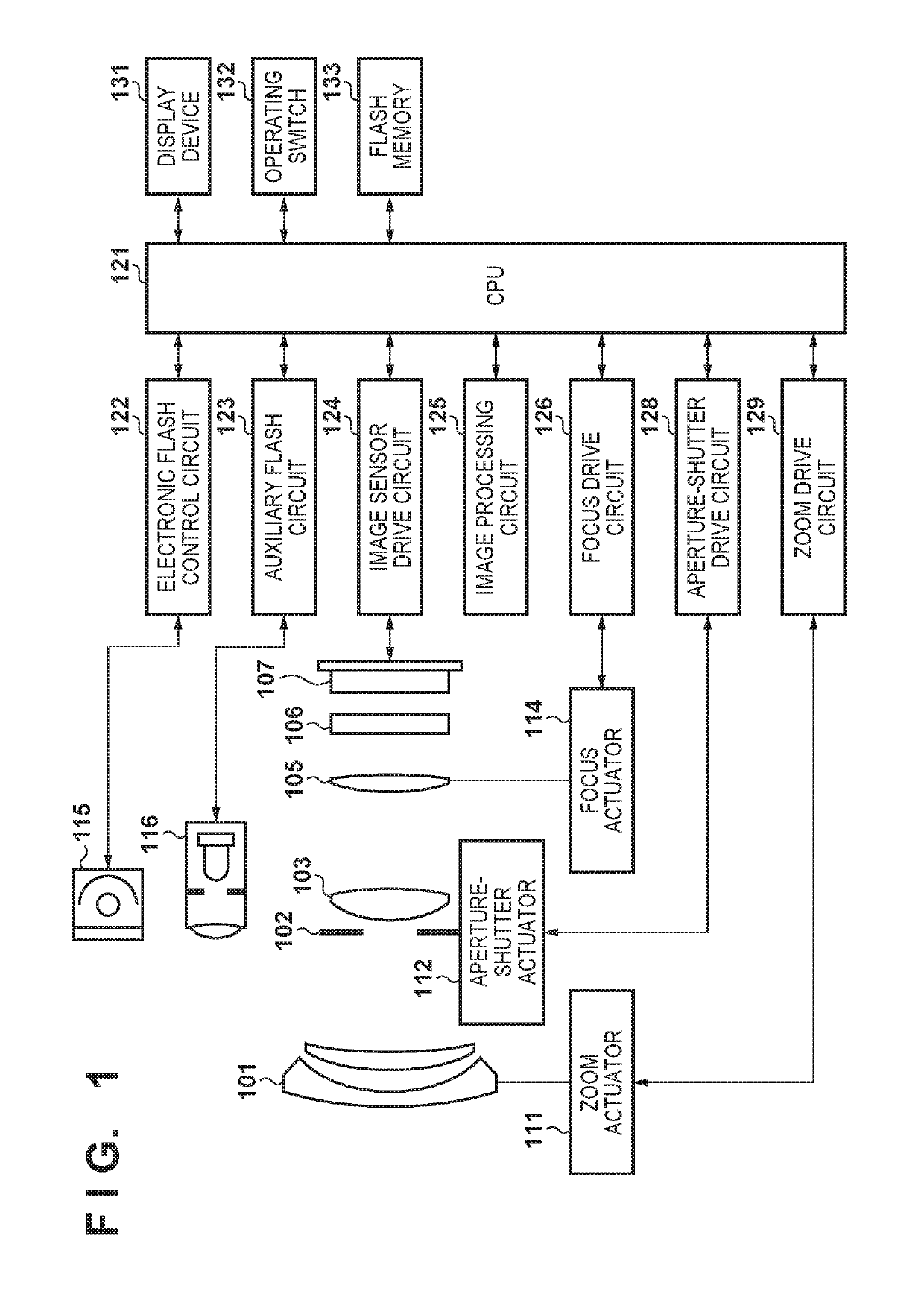
[0023]FIG. 1 is a diagram showing a brief configuration of a camera as an example of an image capturing apparatus having an image sensor according to an embodiment of the present invention. In FIG. 1, a first lens group 101 is disposed on the front end of an imaging optical system, and supported so as to be movable forward and backward along an optical axis. An aperture-shutter 102 adjusts the diameter of its opening, thereby adjusting the amount of light during image sensing, and also has a function to adjust the exposure time during still image sensing. The aperture-shutter 102 and a second lens group 103 move together forward and backward along the optical axis, and, in conjunction with the forward and backward movement of the first lens group 101, provide a magnification change effect (a zoom function).

[0024]A third lens group 105 (focus lens) carries out focus adjustment by moving forward and backward along the optical axis. A low-pass optical filter 106 is...

second embodiment

[0084]Next, a second embodiment of the present invention will be described. In the first embodiment, the lens ID or the group ID of the imaging optical system is used as the lens information of the imaging optical system, and weights (addition coefficient set) when adding signals output from a plurality of focus detection pixels having different spectral sensitivities from each other are changed according to the lens information. On the other hand, in the second embodiment, weights (addition coefficient set) for adding signals of a plurality of focus detection pixels having different spectral sensitivities from each other are changed based on chromatic aberration of magnification information as lens information of the imaging optical system. Since the second embodiment is similar to the first embodiment except for changing the weights of the detection signals, the difference will be described, and the description of common points such as the configuration of the camera will be omitt...

third embodiment

[0091]Next, a third embodiment of the present invention will be described. It is known that, in an interchangeable lens type image capturing apparatus, a calibration is performed in a state where a combination of an interchangeable lens and an image capturing apparatus is decided. Accordingly, in the third embodiment, in a state where a combination of interchangeable lens and an image capturing apparatus is decided, proper weights (addition coefficient set) for detected signals are set at the time of calibration. Since the third embodiment is similar to the first embodiment except for changing the weights of the detection signals, the difference will be described, and the description of common points such as the configuration of the camera will be omitted.

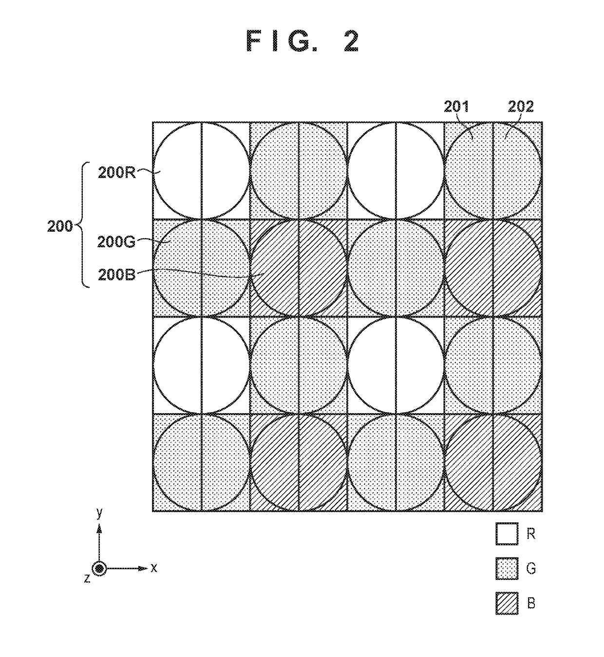
[0092]There are several patterns considered as the addition coefficient sets, and patterns as shown in Table 3 are used in the third embodiment. The pixel layout of the image sensor 107 of the third embodiment has a Bayer arrangeme...


PUM


Abstract

A focus detection apparatus that performs phase difference focus detection based on signals of a plurality of colors obtained from an image sensor, which is covered by color filters of the plurality of colors, that performs photoelectric conversion on light incident on the image sensor via an imaging optical system and outputs electric signals, the apparatus comprising: an acquisition unit that acquires an addition coefficient indicating weights to be applied to the signals of the plurality of colors on the basis of characteristic of chromatic aberration of magnification of the imaging optical system; a generation unit that generates a pair of focus detection signals by performing weighted addition on the signals of the plurality of colors using the addition coefficient; and a detection unit that detects an image shift amount between the pair of focus detection signals.

Description

BACKGROUND OF THE INVENTIONField of the Invention[0001]The present invention relates to a focus detection apparatus and method, and an image capturing apparatus.Description of the Related Art[0002]A phase difference focus detection method (phase difference AF) is known as an automatic focus detection (AF) method used in an image capturing apparatus. The phase difference AF is an AF which is often used in digital still cameras, and some image sensors are used as focus detection sensors. In Japanese Patent Laid-Open No. 2008-52009, in order to perform focus detection based on the pupil division method, a photoelectric conversion unit of each pixel constituting an image sensor is divided into a plurality of portions, and the divided photoelectric conversion units receive light fluxes having passed through different regions of the pupil of the photographing lens via the lens via a microlens.[0003]The phase difference AF can simultaneously detect the focus detection direction and the foc...

Claims


Application Information

Patent Timeline
Patent Type & Authority Patents(United States)
IPC IPC(8): H04N5/232G01J3/02G03B13/00G03B13/36H04N5/369G01J1/42G02B7/34H01L27/146G01J3/28
CPCH04N5/23212G01J1/4209G01J3/0208G01J3/0237G02B7/346G03B13/36H01L27/14627H04N5/3696G01J2003/2806H04N23/56H04N23/672H04N23/67H04N25/704H04N25/70H04N23/10
Inventor MIZUNO, NOBUTAKA
Owner CANON KK
Why Eureka
Try Eureka