
Method and apparatus for polarizing nuclear and electronic spins

a nuclear and electronic spin technology, applied in the field of magnetic resonance, can solve the problems of low noise ratio, low polarization degree, and use of very expensive magnets, and achieve the effect of increasing the sensitivity of the apparatus and methods, and achieving the greater degree of spin polarization

Active Publication Date: 2019-06-25
RES FOUND THE CITY UNIV OF NEW YORK
View PDF11 Cites 2 Cited by
  • Summary
  • Abstract
  • Description
  • Claims
  • Application Information

AI Technical Summary

Benefits of technology

This approach enables a significant increase in spin polarization, enhancing the sensitivity of magnetic resonance measurements and allowing for portable, cost-effective applications in diagnostics and analysis.

Problems solved by technology

For this reason, bulky, very-expensive magnets are used whose sole purpose is to produce the highest possible fractional spin alignment and thus the highest signal-to-noise ratio when probing the smallest amount of sample.
Unfortunately, and even with the strongest possible magnets, the fractional (nuclear) spin alignment is very low, reaching at room temperature a value of approximately 0.005% or less (i.e., in a hypothetical sample of 1 million nuclear spins, the number difference between spins pointing with the field and against it amounts to less than 50).
However, they either work at very low temperatures (10 K and below) or are incapable of generating polarization superior to that obtained with the use of a strong magnet.
Despite these limitations, higher spin polarization is in such high demand that several companies have developed complex (and very expensive) instruments that partly overcome these problems.
Such systems are bulky and costly.

Method used


Image

  • Method and apparatus for polarizing nuclear and electronic spins
  • Method and apparatus for polarizing nuclear and electronic spins
  • Method and apparatus for polarizing nuclear and electronic spins

Examples


Embodiment Construction

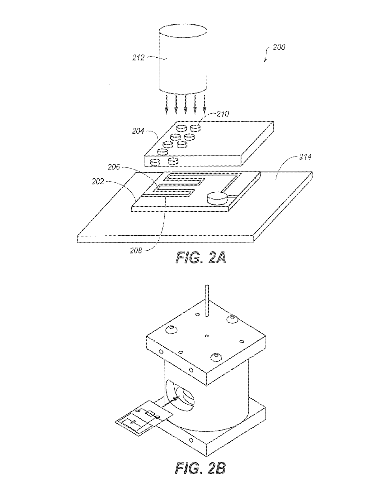
[0023]The technology disclosed in this specification addresses the fractional spin polarization limitation of magnetic resonance. A sample under investigation is brought in direct contact with the surface of a properly treated diamond crystal exposed to continuous green light. A level of polarization of the order 1-10% can be produced depending on the exact parameters. This level of polarization is up to five orders of magnitude higher than that possible by the application of an external magnetic field under traditional conditions. Because the signal observed in magnetic resonance is proportional to the level of spin polarization attained, the disclosed technology enables the characterization of samples with unprecedented sensitivity. Since only a small magnetic field is required (e.g., produced via permanent ferromagnetic material), the system may be portable. Example applications include the detection of contaminants or pathogens within fluids, the high-throughput characterization...


PUM

PropertyMeasurementUnit
magnetic fieldaaaaaaaaaa
widthaaaaaaaaaa

Abstract

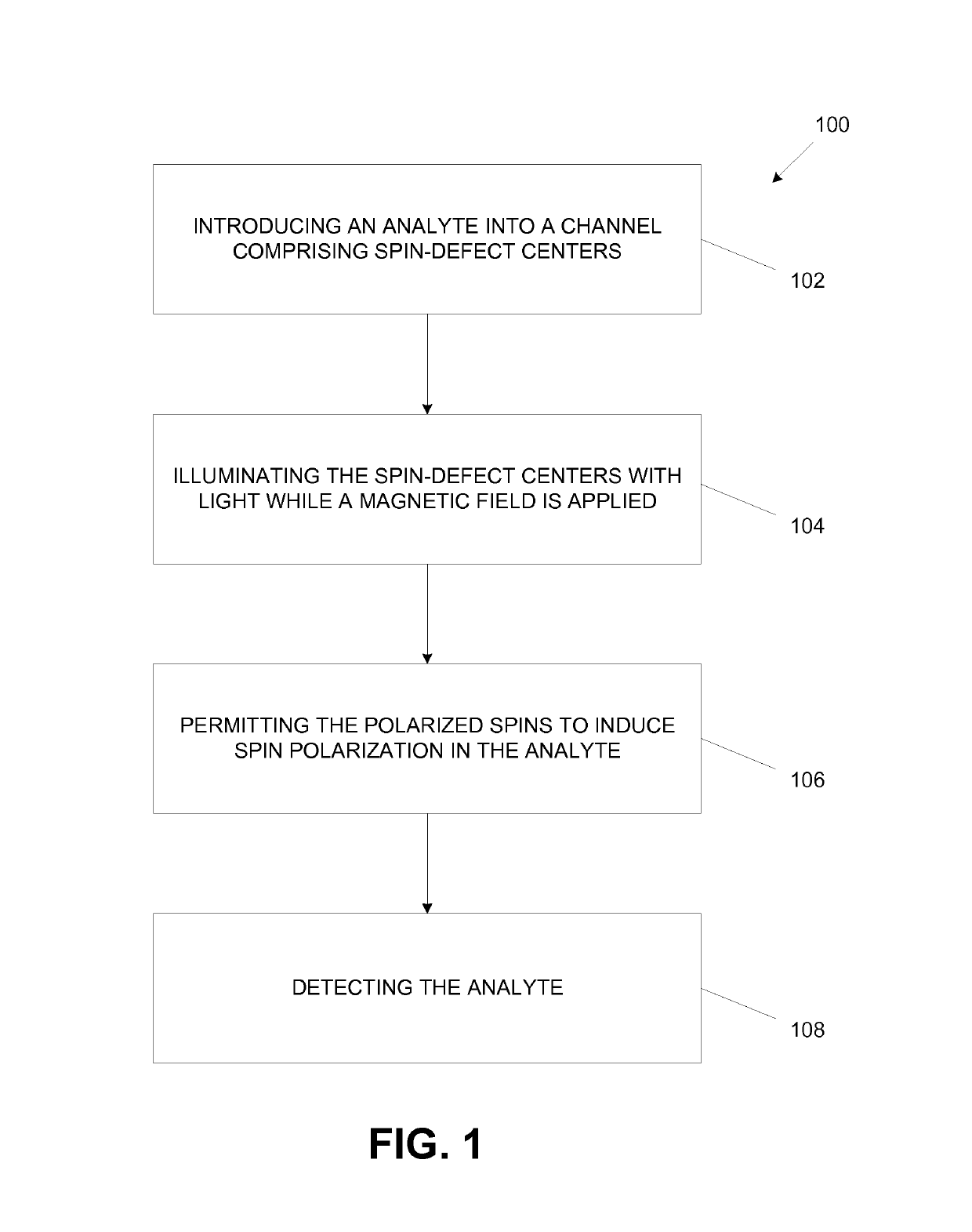
A method and apparatus for polarizing nuclear or electronic spins is disclosed. An analyte is passed near a surface that has a plurality of spin defect centers implanted within 10 nm of the surface. The spin defect centers are exposed to a magnetic field and illumination to produce polarized spins. The polarized spins then induce spin polarization in the analyte.

Description

STATEMENT OF FEDERALLY SPONSORED RESEARCH OR DEVELOPMENT[0001]This invention was made with government support under contract no. 1111410 and 1309640 awarded by the National Science Foundation (NSF). The government has certain rights in the invention.CROSS-REFERENCE TO RELATED APPLICATIONS[0002]This application is a non-provisional of U.S. Patent Application Ser. No. 61 / 808,664 (filed Apr. 5, 2013), the entirety of which is incorporated herein by reference.BACKGROUND OF THE INVENTION[0003]The subject matter disclosed herein relates to magnetic resonance including nuclear magnetic resonance and electron magnetic resonance.[0004]Magnetic resonance (MR) is one of the most powerful analytical tools employed in the physical, biological, and materials sciences, as well as in medical diagnostics. Nuclei and electrons in a sample under investigation may be thought of as microscopic compasses called spins. In a MR device, a magnet is used to induce spin polarization in the sample (i.e., to pa...

Claims


Application Information

Patent Timeline
Patent Type & Authority Patents(United States)
IPC IPC(8): G01R33/30G01R33/28G01N24/12G01R33/62G01N24/08
CPCG01R33/302G01R33/282G01R33/62G01N24/12G01R33/307G01N24/08
Inventor MERILES, CARLOS A.
Owner RES FOUND THE CITY UNIV OF NEW YORK
Learn More