
Circuit protection system and method

a circuit protection and circuit technology, applied in the field of electronic circuits, can solve the problems of difficult to choose a particular foundry, and complicated processes for electronic components

Active Publication Date: 2019-06-25
SECURE IC
View PDF6 Cites 8 Cited by
  • Summary
  • Abstract
  • Description
  • Claims
  • Application Information

AI Technical Summary

Benefits of technology

This approach provides a low-cost, provable, and dynamic solution that effectively prevents Trojan horse attacks by encoding variables with random bit vectors, making it difficult for attackers to extract sensitive information and ensuring the circuit's integrity even after fabrication.

Problems solved by technology

The fabrication of electronic components necessitates extremely complex processes.
Moreover, the fabrication of such components necessitates a complex and costly infrastructure, such as foundry type factories for manufacturing the electronic circuits of these electronic components, generally from silicon and using masks.
It then becomes difficult to choose a particular foundry.
In some technology sectors such a choice may be limited by the absence or guarantees offered by the foundry and in particular the impossibility of being sure that the foundry operator has no malicious intent in the context of the fabrication of the electronic components.
For example, it is difficult to check if the foundry:produces more samples than requested in order to sell them on a grey market (this is the concept known as overbuilding);copies the blueprints of the electronic components in order to resell them;modifies the blueprints of the electronic circuits before fabricating them (known as counterfeiting).
Modification of the electronic circuits is a particularly sensitive threat.
Its reliability is also difficult to quantify.
In fact, false positives (detection of a Trojan horse that in reality does not exist) and false negatives (non-detection of a Trojan horse that in reality does exist, for example if it is sufficiently discreet) can occur.
However, such a study by reverse engineering the component can prove particularly lengthy and complex if the circuit contains several million gates, which makes it very costly.
In such approaches, to obtain a satisfactory detection capacity, it is necessary to have available a healthy reference sample to carry out difference measurements, which renders the approach more complex and costly.
However, using two foundries is specific to the fabrication of masks for dedicated circuits of ASIC (Application Specific Integrated Circuit) type, induces high logistical costs and reduces production efficiency.
Moreover, although the use of a memory to be configured after fabrication makes it possible to render the functionality dependent on a key, it leads to a high additional cost: it is estimated that an FPGA type reprogrammable area is 40 times larger than a dedicated area.
This method is therefore not protected from a static analysis of the partial structure of the electric circuit (known as a netlist).
Moreover, this protection is static, i.e. there is nothing to prevent a hacker from probing the missing configuration once the component has been customised.
Another prevention solution consists in effecting a high-density placement, which makes it difficult to insert large Trojan horses (Shivam Bhasin, Jean-Luc Danger, Sylvain Guilley, Xuan Thuy Ngo, and Laurent Sauvage.
Although such a solution based on an increase in the placement density makes inserting a large Trojan horse more complicated, it is possible in practice for a hacker to produce and to insert a sufficiently powerful Trojan horse into a target circuit, despite such a solution.
However, such Trojan horse insertion prevention techniques prove costly and / or relatively unprovable.
In fact, obfuscation, like white box cryptography, is by its nature inherently not provable.

Method used


Image

  • Circuit protection system and method
  • Circuit protection system and method
  • Circuit protection system and method

Examples


first embodiment

[0173]In a first embodiment, it is possible to use the code D in place of the code E to code the variable y (while the supplementary code F of the code E is equal to the binary code C), which yields y′=yH, the fault detector carrying out the tests zK=y′K and y′J=0. The minimum Hamming weight cost of a non-detectable attack is then equal to min(dC, dD). In the case where the faults on the coded variables z and y′ are uniformly distributed, the probability of detection becomes:

[0174]2dim⁢(𝔽2n)-12dim⁢(𝔽2n).

second embodiment

[0175]Alternatively, in a second embodiment, the code E may be made equal to the binary code C while the supplementary code F of the code E is equal to the supplementary code D of the code C, the variable y of (n−k) bits being transformed into a variable yk of n bits and the encoded variable y′ being of size n and equal to ykH.

[0176]In particular, if n−k≤k, it is possible to construct a vector yk of size k on the basis of the variable y of size n−k, for example by concatenating y with constant or random data. It is then possible to code yk with the code C in place of the code E. The coded variable y′ then becomes y′=ykG=(y↑k)G where the operator ↑k designates the operation consisting in increasing the size of the vector up to k, for example by data padding. The fault detector 12 then performs a first test zK=(y′J) ↓n-k in which the operator ↓n-k designates the operation of selecting the n−k bits corresponding to y in yk. The fault detector 12 carries out the second test y′K=0.

[0177]...


PUM


Abstract

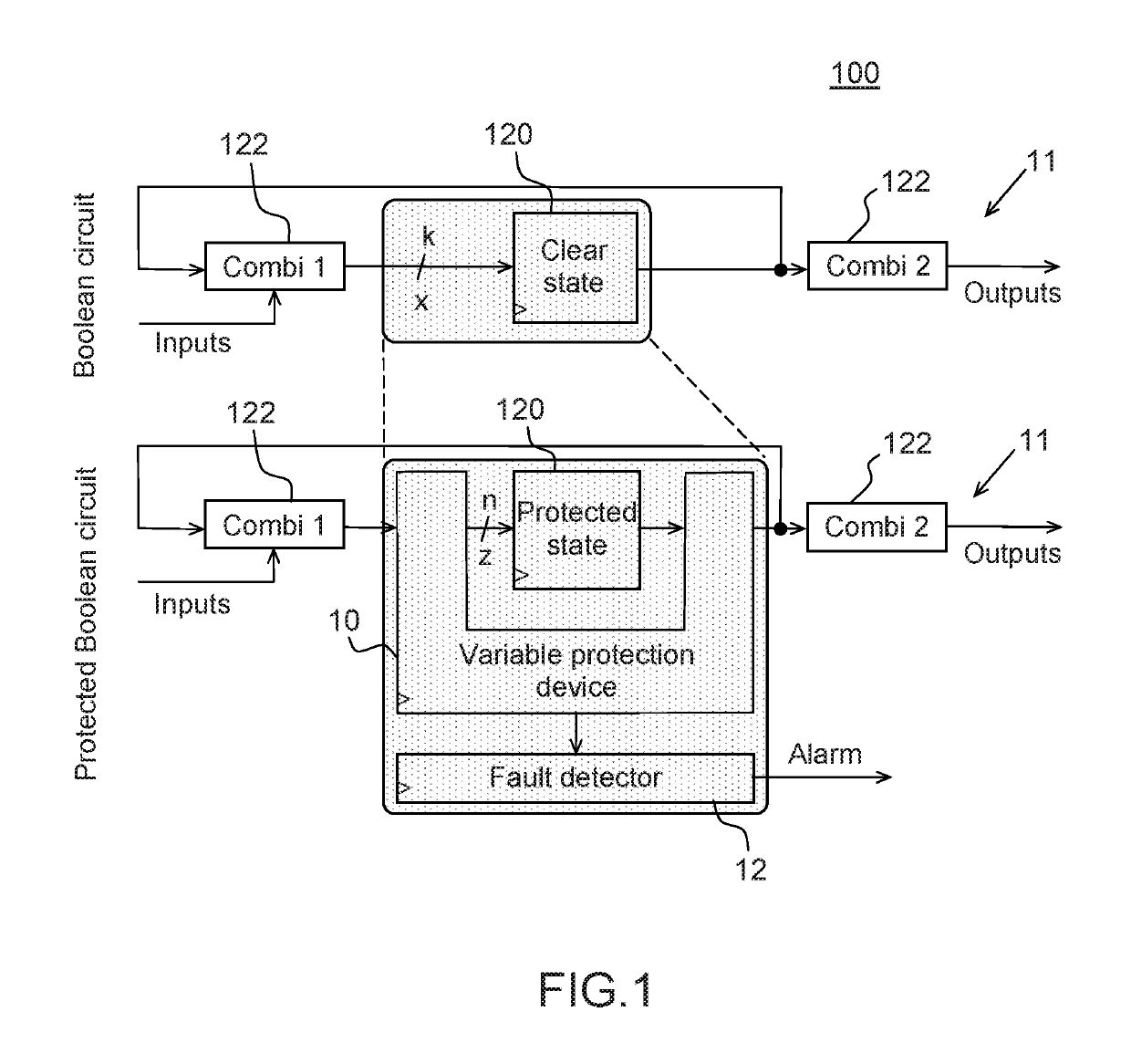
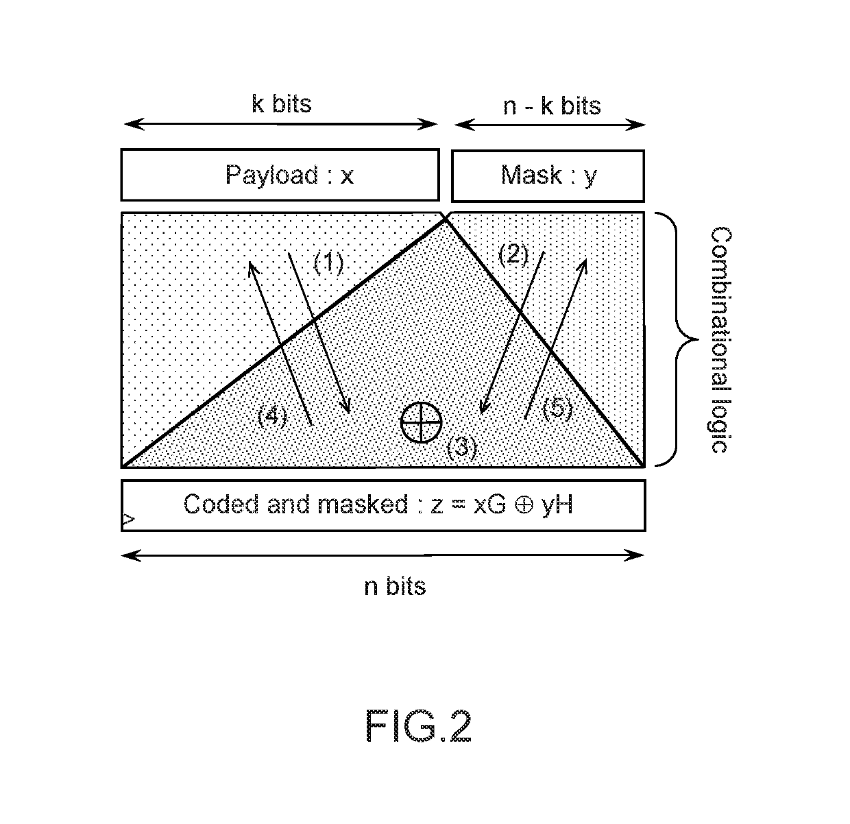
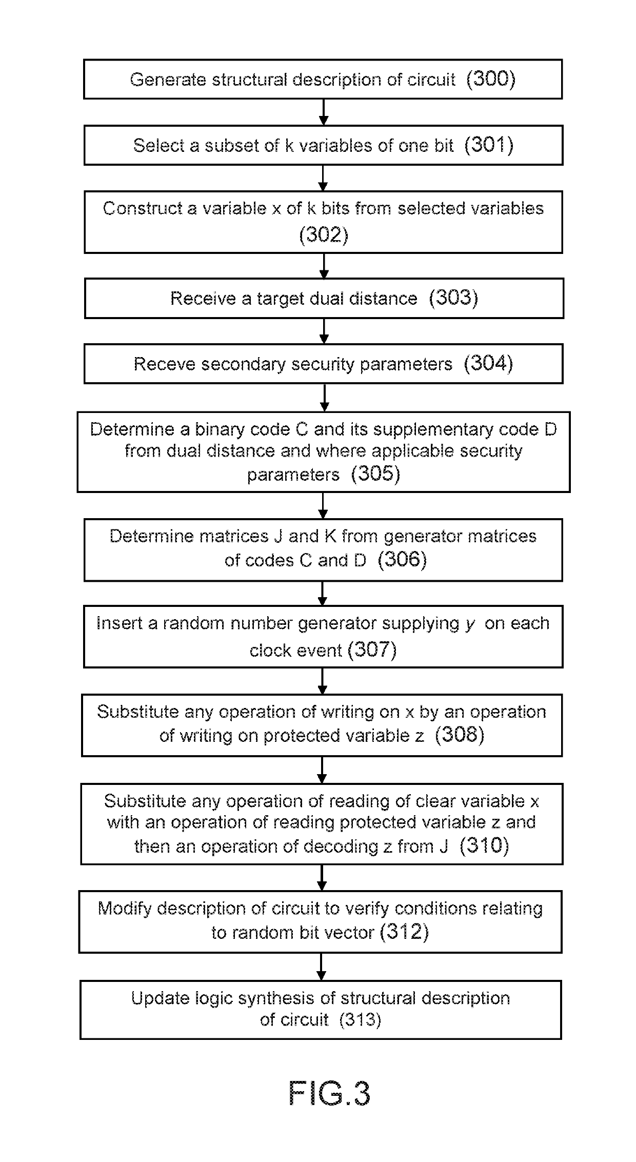
The invention proposes a method of protection of a Boolean circuit associated with a structural description of the circuit comprising elementary Boolean variables, each represented by one bit, the method comprising the steps consisting in:selecting a set of k elementary Boolean variables of the circuit as a function of predefined selection criteria,constructing a variable x represented by k bits by concatenation of the k selected variables in accordance with a chosen order,determining a binary code C comprising a set of code words and belonging to a given vector space and the supplementary code D of said binary code C as a function of a condition bearing on the dual distance of said supplementary code D, said binary code C having a length n and a size 2k, where k designates the number of bits representing said variable x;substituting the variable x in the structural description of the Boolean circuit with a protected variable z represented by n bits so that:any operation of writing on the variable x in the circuit is substituted with an operation of writing on the variable z, the variable z being generated by adding the variable x encoded by said code C to a random bit vector y encoded by the supplementary code D, andany operation of reading the variable x in the circuit is substituted with an operation of reading the value of the protected variable z and an operation of decoding said read value of the protected variable z using a decoding matrix J of size (n×k) determined from the binary code C and the supplementary code D of the binary code C.

Description

TECHNICAL FIELD[0001]The present invention is generally concerned with electronic circuits and in particular systems and methods for protecting such electronic circuits.PRIOR ART[0002]The fabrication of electronic components necessitates extremely complex processes. Moreover, the fabrication of such components necessitates a complex and costly infrastructure, such as foundry type factories for manufacturing the electronic circuits of these electronic components, generally from silicon and using masks. It has in particular been observed that the more developed the technology of the electronic components, the smaller the number of factories required for their fabrication. Such factories in small numbers must then function with strong constraints so as to be able to process the different types of electronic components that are entrusted to them, such as availability and production throughput constraints, for example. It then becomes difficult to choose a particular foundry. To optimise...

Claims


Application Information

Patent Timeline
Patent Type & Authority Patents(United States)
IPC IPC(8): G09C1/00H04L9/00G06F11/22G06F11/263G06F21/75G06F21/71G06F21/56G06F21/55
CPCG06F21/75G06F11/22G06F11/263G06F21/56G06F21/71H04L9/002G09C1/00H04L2209/12G06F21/55G06F2221/034H04L2209/046
Inventor GUILLEY, SYLVAINPORTEBOEUF, THIBAUTDANGER, JEAN-LUC
Owner SECURE IC
Learn More