Supercharge Your Innovation With Domain-Expert AI Agents!

Solar cell assembly I

a solar cell and assembly technology, applied in the field of solar cell assembly, can solve the problems of thermal conductivity, thermal conductivity, tedious and time-consuming back side contact of solar cells with the substrate of sca, etc., and achieve the effect of obtaining quick and reliable results

Active Publication Date: 2019-06-25
SAINT AUGUSTIN CANADA ELECTRIC
View PDF27 Cites 0 Cited by
  • Summary
  • Abstract
  • Description
  • Claims
  • Application Information

AI Technical Summary

Benefits of technology

The patent text describes a method for connecting a bonding pad and a cooling substrate in a solar cell assembly without using adhesive. Instead, a direct solid state connection is achieved, which improves reliability and reduces the number of parts used in the assembly. The bonding pad and cooling substrate can be joined laser welding, ultrasonic welding, resistance welding, or other solid state connection methods. Using these geometric shapes, multiple bonding pads can be arranged closely together, which increases the overall efficiency of the assembly. The bonding pad may also have a contact surface for contacting the solar cell. This method simplifies the process of attaching solar cells to a cooling substrate and reduces the risk of forming deleterious elements. Overall, this innovation improves the reliability and performance of solar cell assemblies.

Problems solved by technology

A critical issue is the back side contacting of the solar cell with the substrate of the SCA.
Conventionally, a continuous single substrate functioning as a cooling substrate is contacted to the back side of a solar cell by means of selective noble metal (e.g., gold) deposition that represents a tedious and time-consuming, as well as expensive processing step.
The provision of a number of electrically isolating material elements results in poor thermal conductivity and, thus, an inefficient overall thermal connection of the solar cell.
Moreover, provision of materials of different material characteristics implies higher expenses and a plurality of connection regions and, therefore, may result in a significant deterioration of the (long-life) reliability of the manufactured SCA due to galvanic elements or thermo-mechanic stress.

Method used


Image

  • Solar cell assembly I
  • Solar cell assembly I
  • Solar cell assembly I

Examples


Embodiment Construction

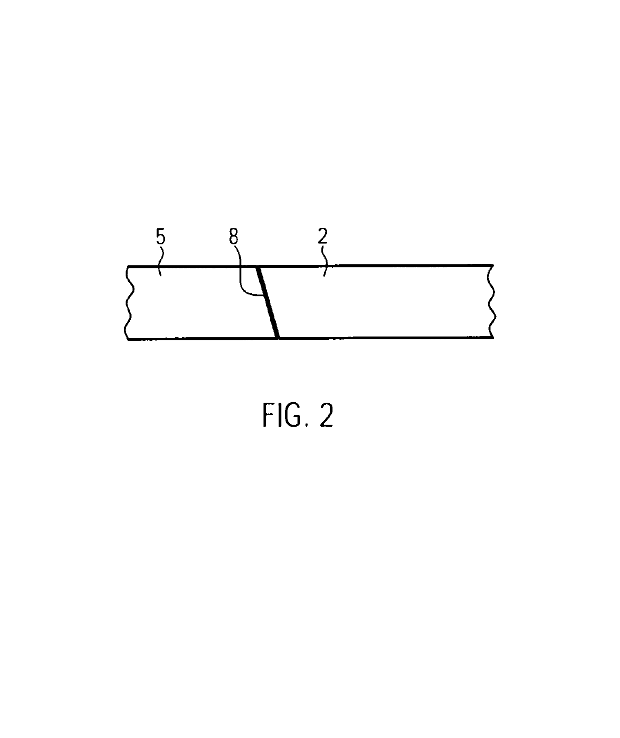
[0053]An SCA configuration manufactured in accordance with the present invention is illustrated in FIGS. 1a (top view) and 1b (side view). The SCA comprises a cooling substrate 5 and a bonding pad 2 planar joined to the cooling substrate 5. As can be seen in FIG. 1b the bonding pad 2 is flush with the cooling substrate 5 with no (particularly, no insulating) material between them. In fact, the bonding pad 2 and the cooling substrate 5 are subject to a solid state bond, thereby providing a reliable long-term durable connection unprecedented in the art. It is preferred that the bonding pad 2 and the cooling substrate 5 are made of the same material. According to an example this material is an aluminum alloy, in particular, a 99.5% aluminum alloy. Thermal stresses and galvanic elements between the bonding pad 2 and the cooling substrate 5 are avoided by the choice of the same material.

[0054]In principle, the cooling substrate 5 consists of a plane metal and shall provide thermal coolin...


PUM


Abstract

The present invention relates to a solar cell assembly, comprising a solar cell attached to a bonding pad and a cooling substrate and wherein the bonding pad and the cooling substrate are joined to each other in a planar and flush manner such that the bonding pad and the cooling substrate are connected to each other in the form of a solid state connection. The invention further relates to a solar cell assembly that includes a solar cell attached to a bonding pad and a cooling substrate and wherein the bonding pad is attached on a surface of the cooling substrate such that the bonding pad and the cooling substrate are connected to each other in the form of a solid state connection. Also, a method for manufacture of such solar cell assemblies is provided.

Description

CROSS-REFERENCE TO RELATED APPLICATIONS[0001]This application is a national phase entry under 35 U.S.C. § 371 of International Patent Application PCT / EP2011 / 000840, filed Feb. 22, 2011, designating the United States of America and published in English as International Patent Publication WO 2011 / 104001 A1 on Sep. 1, 2011, which claims the benefit under Article 8 of the Patent Cooperation Treaty and under 35 U.S.C. § 119(e) to European Patent Application Serial No. 10001965.2, filed Feb. 25, 2010, the disclosure of each of which is hereby incorporated herein in its entirety by this reference.FIELD OF THE INVENTION[0002]The present invention relates to a solar cell assembly and the manufacture of the same, and, particularly, the invention relates to a solar cell assembly comprising a cooling substrate and a bonding pad for the attachment of a solar cell.BACKGROUND OF THE INVENTION[0003]Photovoltaic or solar cells are designed for converting the solar radiation to electrical current. In...

Claims


Application Information

Patent Timeline
Patent Type & Authority Patents(United States)
IPC IPC(8): H01L31/02H01L31/044H01L31/052
CPCH01L31/052H01L31/02008H01L31/044H01L2224/48091H01L2224/48137Y02E10/50H01L2224/73265H01L2924/00014
Inventor ZIEGLER, MARTINVAN RIESEN, SASCHA
Owner SAINT AUGUSTIN CANADA ELECTRIC
Features
  • R&D
  • Intellectual Property
  • Life Sciences
  • Materials
  • Tech Scout
  • Unparalleled Data Quality
  • Higher Quality Content
  • 60% Fewer Hallucinations
Learn More