Nozzle for producing microparticles

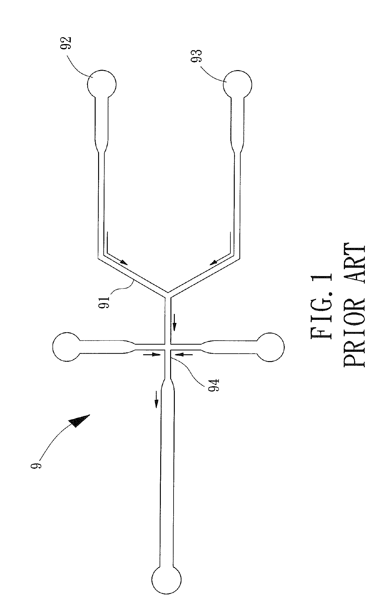
a technology of microparticles and nozzles, which is applied in the direction of spray nozzles, liquid spraying apparatus, granulation by liquid drop formation, etc., can solve the problems that the conventional micro fluid passageway structure b>9/b> cannot easily proceed with mass production, and achieves the effect of effectively transmitting vibrational energy, reducing the purchasing cost of nozzles, and improving use convenien

Active Publication Date: 2019-07-02
METAL INDS RES & DEV CENT
View PDF2 Cites 1 Cited by
  • Summary
  • Abstract
  • Description
  • Claims
  • Application Information

AI Technical Summary

Benefits of technology

[0008]A nozzle for producing microparticles according to the present disclosure includes a nozzle body and a tube assembly. The nozzle body includes a first end and a second end opposite to the first end. The nozzle body further includes a through-hole, an oscillating device, and an amplifying portion. The oscillating device is connected to the amplifying portion. The amplifying portion is located between the first end and the second end. The through-hole extends from the first end of the nozzle body through the amplifying portion and extends through the second end of the nozzle body. The tube assembly is mounted in the through-hole and includes a first tube and a second tube surrounded by the first tube. A first fluid passageway is defined between the first tube and the second tube. A second fluid passageway is defined in the second tube. The first fluid passageway and the second fluid passageway are configured to respectively permit two fluids to flow from the first end toward the second end of the nozzle body. The first tube includes a first end forming a first filling port intercommunicated with the first fluid passageway and a second end forming a plurality of first outlet ports intercommunicated with the first fluid passageway. The second tube includes a first end forming a second filling port intercommunicated with the second fluid passageway and a second end forming a second outlet port intercommunicated with the second fluid passageway. A formation space is defined between the second outlet port and the plurality of first outlet ports. By the design of the tube assembly having the first tube and the second tube, a dual-layer liquid film is formed on each first outlet port. Furthermore, by using the vibrational energy generated by the combined action of the piezoelectric portion and the amplifying portion, the thickness of the dual-layer liquid film on each first outlet port is reduced, thereby forming dual-layer microdroplets that fall into the tank. Thus, the present disclosure achieves the effect of mass production of microparticles of a uniform size. In an example, each of the plurality of outlet ports has a diameter, with two adjacent outlet ports having a wall spacing therebetween, and the wall spacing is at least two times the diameter. Thus, the liquid films on the first outlet ports can more easily absorb the vibrational energy generated by the piezoelectric portion and the amplifying portion to form a standing wave.
[0009]In an example, the first tube includes an end formed by a sleeve having the plurality of first outlet ports. Thus, a worker can replace the sleeve according to needs to improve use convenience. Furthermore, it is not necessary to replace the whole nozzle, thereby reducing the purchasing costs of the nozzle.
[0010]In an example, the oscillating device includes a piezoelectric portion. The through-hole extends from the first end of the nozzle body through the piezoelectric portion and the amplifying portion in sequence and extends through the second end of the nozzle body. Thus, the contact area between the piezoelectric portion and the amplifying portion can be increased to effectively transmit the vibrational energy to the amplifying portion.

Problems solved by technology

Although the above conventional micro fluid passageway structure 9 can form microparticles with more uniform diameters, the conventional micro fluid passageway structure 9 cannot easily proceed with mass production.

Method used


Image

  • Nozzle for producing microparticles
  • Nozzle for producing microparticles
  • Nozzle for producing microparticles

Examples


Embodiment Construction

[0019]With reference to FIGS. 2 and 3, a nozzle for producing microparticles of an embodiment according to the present disclosure includes a nozzle body 1 and a tube assembly 2. The nozzle body 1 includes a through-hole 11. The tube assembly 2 is mounted in the through-hole 11.

[0020]Specifically, the nozzle body 1 has a first end 1a and a second end 1b opposite to the first end 1a. The nozzle body 1 further includes an oscillating device and an amplifying portion 13. The oscillating device can be directly or indirectly connected to the amplifying portion 13. The amplifying portion 13 is located between the first end 1a and the second end 1b. The through-hole 11 extends from the first end 1a through the amplifying portion 13 and extends through the second end 1b. In this embodiment, the oscillating device includes a piezoelectric portion 12. When the piezoelectric portion 12 receives high frequency electric energy from a supersonic wave generator G (see FIG. 5), the high frequency el...


PUM

PropertyMeasurementUnit
diameteraaaaaaaaaa
diameteraaaaaaaaaa
outer diameteraaaaaaaaaa

Abstract

A nozzle for producing microparticles includes a nozzle body having an oscillating device and an amplifying portion connected to the oscillating device and located between first and second ends of the nozzle body. A through-hole extends from the first end through the amplifying portion and the second end. A tube assembly is mounted in the through-hole and includes first and second tubes between which a first fluid passageway is defined. A second fluid passageway is defined in the second tube. Two ends of the first tube respectively form a first filling port and a plurality of first outlet ports both of which intercommunicate with the first fluid passageway. Two ends of the second tube respectively form a second filling port and a second outlet port both of which intercommunicate with the second fluid passageway. A formation space is defined between the second outlet port and the first outlet ports.

Description

CROSS REFERENCE TO RELATED APPLICATIONS[0001]The application claims the benefit of Taiwan application serial No. 105134610, filed Oct. 26, 2016, the subject matter of which is incorporated herein by reference.BACKGROUND1. Technical Field[0002]The present disclosure relates to a nozzle for producing microparticles and, more particularly, to a nozzle for mass production of microparticles.2. Description of the Related Art[0003]Microparticles, also known as microspheres, are spherical particles having a diameter ranging from 1 μm to 1000 μm, are generally used as microcarriers for releasing drugs, and have become one of the emerging drug delivery technologies due to the characteristics of targeting, controlled release, stability, and surface modifiability.[0004]Since the diameters of microparticles are small, the first aim is to form microparticles of uniform diameters to make each microparticle have the same drug releasing effect. For example, a conventional micro fluid passageway stru...

Claims


Application Information

Patent Timeline
Patent Type & Authority Patents(United States)
IPC IPC(8): B01J2/04B05B1/00B01J2/06
CPCB05B1/00B01J2/06B05B17/0646
Inventor LIU, ZONG-HSINHUNG, CHENG-HANLIN, YING-CHIEHPAN, CHENG-TANGHUANG, YAO-KUNLU, YING-CHENG
Owner METAL INDS RES & DEV CENT
Why Eureka
Try Eureka