Detection of biomagnetic signals using quantum detector arrays

a quantum detector and biomagnetic signal technology, applied in the field of magnetic field sensors, can solve the problems of not increasing in popularity of meg and mri, non-optimal signal detection, and no known way to provide seamless solution, etc., to achieve the effect of convenient movement and small device footprin

Active Publication Date: 2019-07-02
THE UNITED STATES OF AMERICA AS REPRESENTED BY THE SECRETARY OF THE NAVY
View PDF5 Cites 0 Cited by
  • Summary
  • Abstract
  • Description
  • Claims
  • Application Information

AI Technical Summary

Benefits of technology

[0014]The radome can further have a surface, and a window with a layer or layers of thin metallic films deposited by atomic layer deposition (ALD) or any other thin film deposition method can be included. The radome surface can allow for passage of magnetic signals through the window and radome, while at the same time preventing passage of infrared radiation, conduction and convection therethrough. The thin film layer / layers can also work as a frequency selective media, which can function to attenuate undesired frequency (frequencies), while at the same time allowing the passage of electromagnetic signals at frequency (frequencies) of interest to pass therethrough, for further detection by the SQA.
[0015]The HTS JJs can each have a set of operating parameters, and the set of operating parameters for each individual JJ can be adjusted to establish an anti-peak response for the SQA as a whole, that can be at a maximum along a defined response axis. This can allow for detection of biomagnetic fields, which can be extremely small (in the fempto-Tesla range). For operation, the SQA can be oriented using a stand with three degrees of freedom (or as a handheld device on some embodiments) so that the SQIF response axis is orthogonal to the target area of a subject that is emitting biomagnetic signals. The response axis can also be coincident with a longitudinal axis for the cold finger, or it can be perpendicular with the cold finger axis, depending on how many SQA are being used in the probe assembly. The JJs can be made of materials that can have a High-Temperature Superconducting (HTS) operating temperature (75-90° K.), which can obviate the need for extensive thermal radiation shields and can allow for a smaller device footprint, which can call for more convenient movement using the stand, or by hand. It can also allow for the device to be placed much closer to the target area, which can further allow for more detailed observation of the subject biomagnetic signals cited above.

Problems solved by technology

However, there is no known way to provide a seamless solution for a system consisting of a SQIF chip (i.e., an SQA) in conjunction with supporting structures that can allow for obtaining a calibrated transfer function for the broadband information carried by free space electromagnetic waves.
Despite this advantage, MEG and MRI have not increased in popularity to the same extent as other brain imaging modalities, such as electroencephalography (EEG), because the limitations of current MEG systems.
These limitations can include rigid sensor placement (which can cause non-optimal signal detection), expensive magnetic shielded rooms to operate effectively, millions of dollars in cost, and lack of portability due to weight and physical form factor.
The intrinsic limitation of current magnetic field biosensors is due to the sensing element, a Superconducting Quantum Interference Device (SQUID), which is typically coupled to a gradiometer and / or magnetometer allowing the detection of magnetic fields as low as 10-15 Tesla (fempto-Tesla) at millisecond time scales.
Typically, the SQUIDs utilized in existing equipment can only operate in highly magnetically shielded environments and at very low temperatures that can require the use of liquid helium as a cryogen.

Method used


Image

  • Detection of biomagnetic signals using quantum detector arrays
  • Detection of biomagnetic signals using quantum detector arrays
  • Detection of biomagnetic signals using quantum detector arrays

Examples


Embodiment Construction

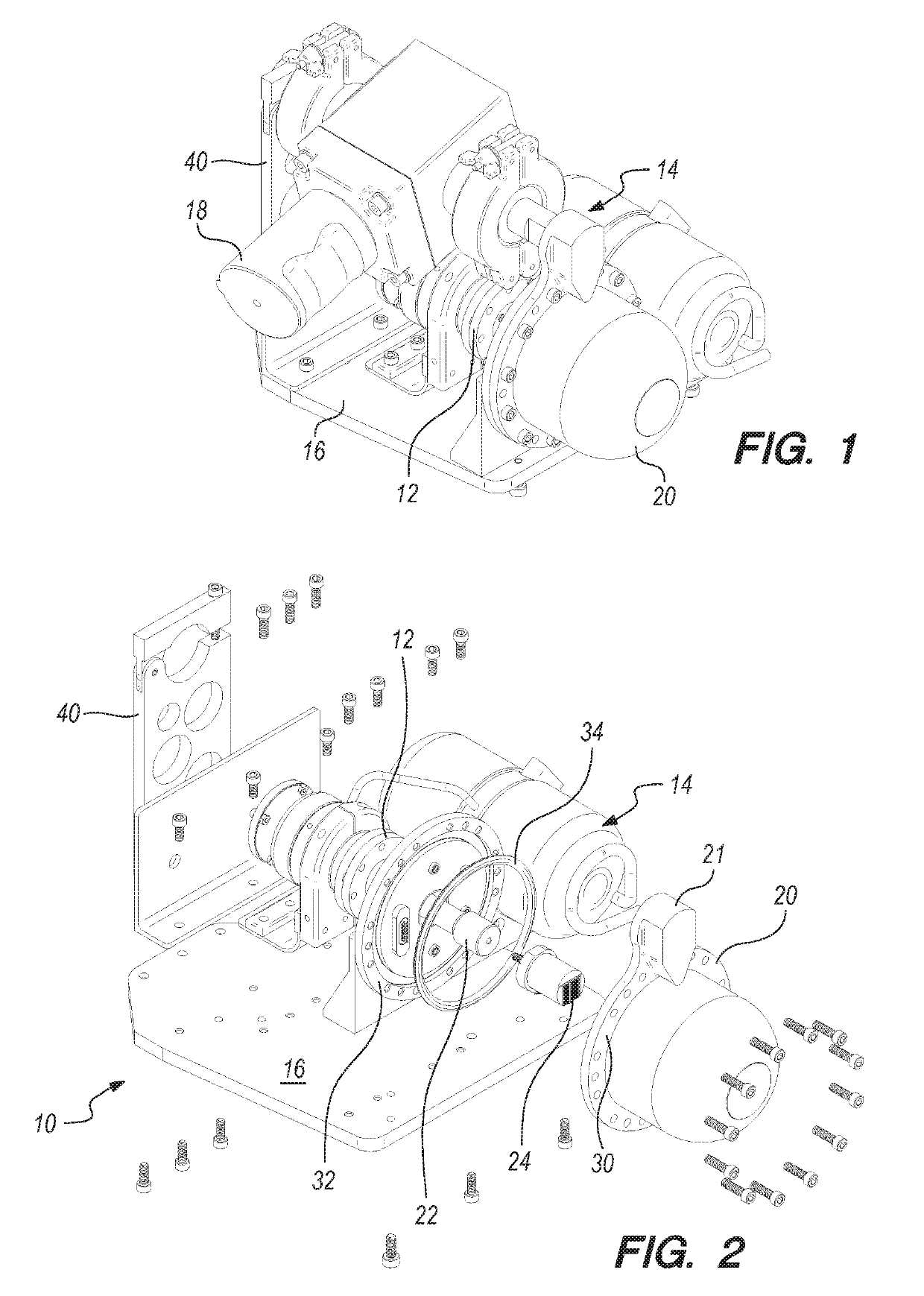
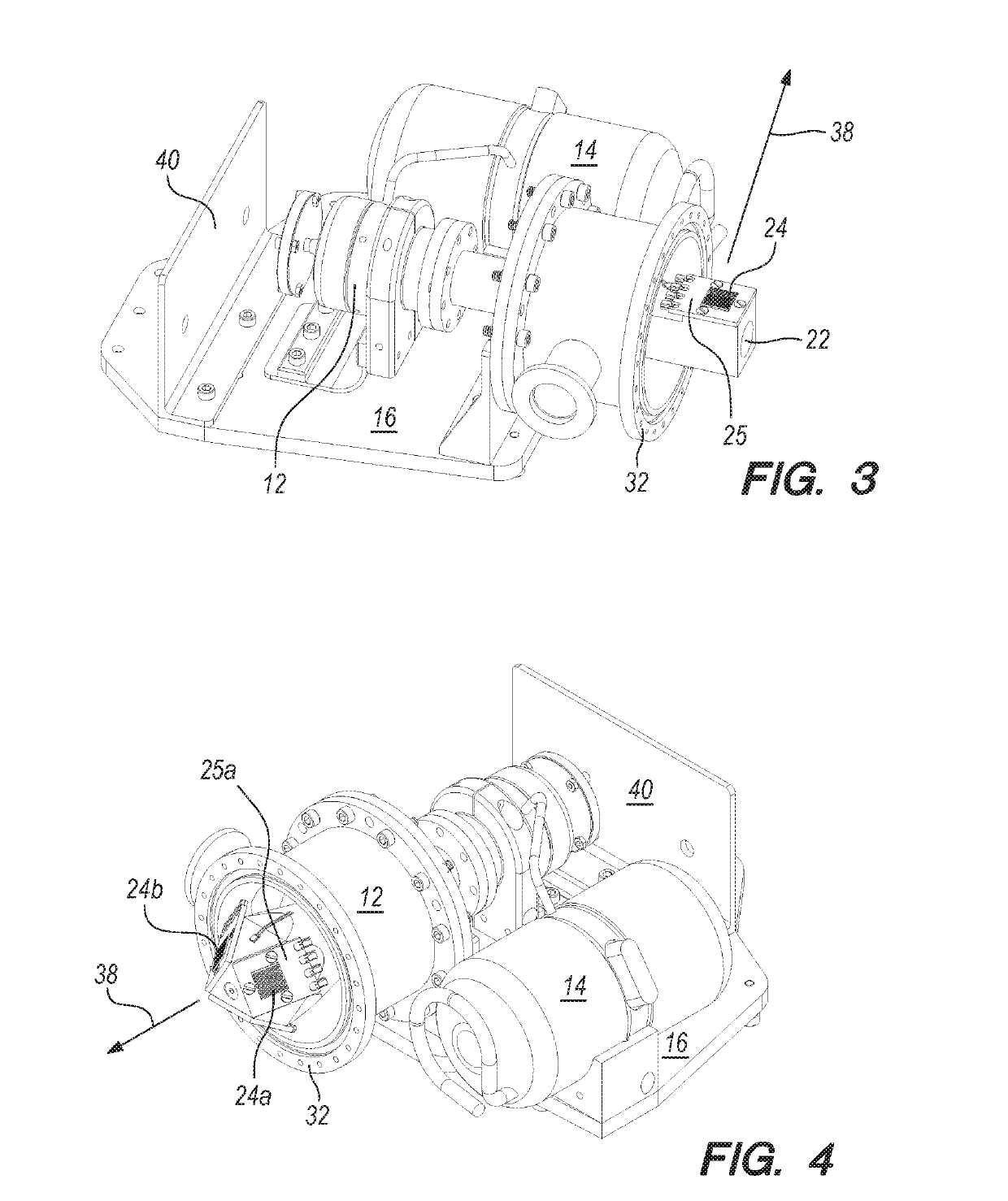
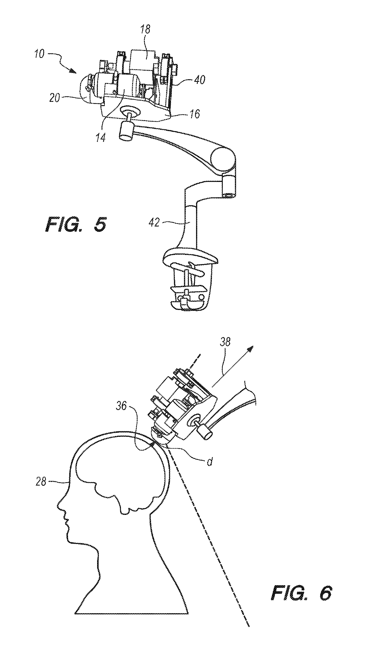
[0030]In brief overview, the method and system described herein consists of a system that can adapt Superconducting Quantum Interference Device (SQUID) arrays (SQAs), which have been previously uniquely designed to operate as an active small electrically broadband superconducting antenna based on detection of quanta of electromagnetic radiation, to detect biomagnetic waves. An embodiment of the detector can include SQAs that can include a front end with a mechanism to control the incoming magnetic field, a thermal management interface, a chip carrier for the sensor with proper functionality to control radiation and provide a clean output of the signal, including channelizer abilities (frequency discrimination) and application specific interfaces. The front end, thermal management interface, and chip carrier can work together as a system that can allow the user to isolate and identify free traveling electromagnetic waves in the far and / or near field region of the sensor.

[0031]An embo...


PUM


Abstract

A biosignal measuring device that can include at least one Super-conducting Quantum Interference Device (SQUID) array (SQA) of High Temperature Superconducting (HTS) Josephson Junctions (JJs). The HTS JJs operating parameters can be adjusted to establish an anti-peak response for the SQA, that can be at a maximum along a defined response axis, for detection of extremely small biomagnetic fields. For operation, the SQA can be maneuvered around a target area of a stationary subject that is emitting biomagnetic signals using a stand with three degrees of freedom, so that the response axis remains orthogonal to the subject target area. The device can further include a radome with an atomic layer deposition (ALD) window on the radome surface. The radome ALD surface can allow for passage of magnetic signals through the ALD window and radome, while simultaneously preventing passage of infrared radiation therethrough.

Description

CROSS REFERENCE TO RELATED APPLICATIONS[0001]This application is a continuation-in-part of U.S. patent application Ser. No. 15 / 360,323, filed Nov. 23, 2016, by Anna Leese de Escobar et al., entitled “System and Method for Controlled, And Selective, Broadband Far and Near Field Radio Frequency Radiation Detector Utilizing Superconducting Quantum Detector Arrays”. The contents of the '323 application are hereby incorporated by reference into this specification.FEDERALLY-SPONSORED RESEARCH AND DEVELOPMENT[0002]The United States Government has ownership rights in this detector. Licensing and technical inquiries may be directed to the Office of Research and Technical Applications, Space and Naval Warfare Systems Center, Pacific, Code 72120, San Diego, Calif., 92152; voice (619) 553-5118; ssc_pac_t2@navy.mil. Reference Navy Case Number 104962.FIELD OF THE INVENTION[0003]This invention pertains generally to magnetic field sensors. More particularly, the invention pertains to sensors that l...

Claims


Application Information

Patent Timeline
Patent Type & Authority Patents(United States)
IPC IPC(8): H01Q1/36G01R33/035A61B5/04
CPCG01R33/0354H01Q1/364G01R33/035A61B5/04008A61B5/245
Inventor DE ANDRADE, MARCIO C.LEESE DE ESCOBAR, ANNAWIEDEMEIER, BRANDON J.LUKOS, JAMIE R.KASA, SHANNONYANAGI, MATTHEW A.
Owner THE UNITED STATES OF AMERICA AS REPRESENTED BY THE SECRETARY OF THE NAVY
Why Eureka
Try Eureka