Water feeding method, water feeding system implementing said method, and steam generating facility provided with water feeding system

a technology of water feeding system and water feeding method, which is applied in the direction of steam generation using hot heat carriers, lighting and heating apparatus, and turbine/propulsion fuel heating. it can solve the problems of water flashing, line itself or a device or the like connected to the line, and water that has barely been cooled by the fuel. it can suppress the change of an operation condition of a system

Active Publication Date: 2019-07-16
MITSUBISHI POWER LTD
View PDF18 Cites 3 Cited by
  • Summary
  • Abstract
  • Description
  • Claims
  • Application Information

AI Technical Summary

Benefits of technology

[0056]According to an aspect of the present invention, even when an amount of heat exchanged between water and a medium suddenly decreases significantly, a change of an operation condition of a system can be suppressed while flashing of the water is prevented from occurring.

Problems solved by technology

Thus, the pressure of the water that has barely been cooled by the fuel is reduced as the water enters into the feed water line or in the course of entering into the feed water line, which causes the water to flash.
When the water flashes inside the feed water line, there is a risk that the line itself or a device or the like connected to the line may be damaged.

Method used


Image

  • Water feeding method, water feeding system implementing said method, and steam generating facility provided with water feeding system
  • Water feeding method, water feeding system implementing said method, and steam generating facility provided with water feeding system
  • Water feeding method, water feeding system implementing said method, and steam generating facility provided with water feeding system

Examples


first embodiment

[0064]A first embodiment of a combined cycle plant provided with a water feeding system according to the present invention will be described below with reference to FIG. 1 to FIG. 4.

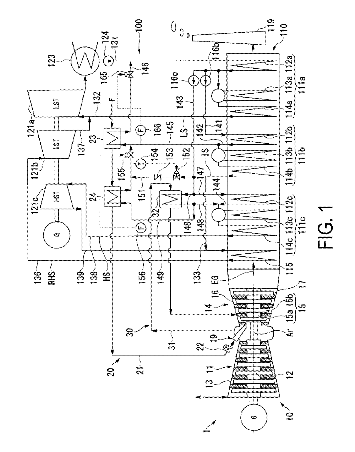
[0065]As illustrated in FIG. 1, the combined cycle plant of the present embodiment includes a gas turbine installation 1, and an exhaust heat recovery facility 100 that recovers the heat of an exhaust gas EG from the gas turbine installation 1.

[0066]The gas turbine installation 1 includes a gas turbine 10, a fuel supply system 20 that supplies a fuel F to the gas turbine 10, and a component cooling system 30 that cools hot parts of the components forming the gas turbine 10.

[0067]The gas turbine 10 includes a compressor 11 that compresses air A, a combustor 19 that combusts the fuel F in the air compressed by the compressor 11 to generate combustion gas, and a turbine 14 that is driven by the high-temperature high-pressure combustion gas. The compressor 11 includes a compressor rotor 12 that rotates aroun...

second embodiment

[0116]A second embodiment of the combined cycle plant provided with the water feeding system according to the present invention will be described below with reference to FIG. 5 and FIG. 6.

[0117]As illustrated in FIG. 5, the combined cycle plant of the present embodiment is formed by adding a cooling water injecting line 161, a cooling water flow rate adjustment valve 162, a check valve 163, and a thermometer 164 to the combined cycle plant of the first embodiment, and the rest of the configuration is basically the same as that of the first embodiment.

[0118]One end of the cooling water injecting line 161 is connected to the intermediate-pressure water line 141, and the other end of the cooling water injecting line 161 is connected to the intermediate-pressure water collection line 146 at a position located between the first fuel preheater 23 and the collected water flow rate adjustment valve 165. The cooling water flow rate adjustment valve 162 and the check valve 163 are both provid...

modified example

[0137]In each of the water feeding systems 50 and 60 of the above-described embodiments, the flow rate of the water is detected by the flow rate meters 156 and 166, and feedback control is performed so as to cause the flow rate detected by the flow rate meters 156 and 166 to become the target flow rate. However, the flow rate of the water need not necessarily be detected by the flow rate meters 156 and 166. In this case, the target flow rate of the water is set in accordance with the operation conditions of the gas turbine 10, such as a load of the gas turbine 10, for example, and feedforward control is performed so as to cause an actual flow rate of the water to become the target flow rate of the water.

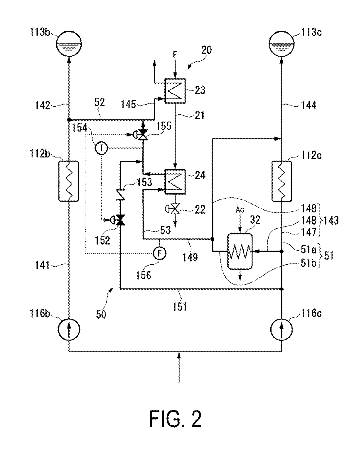
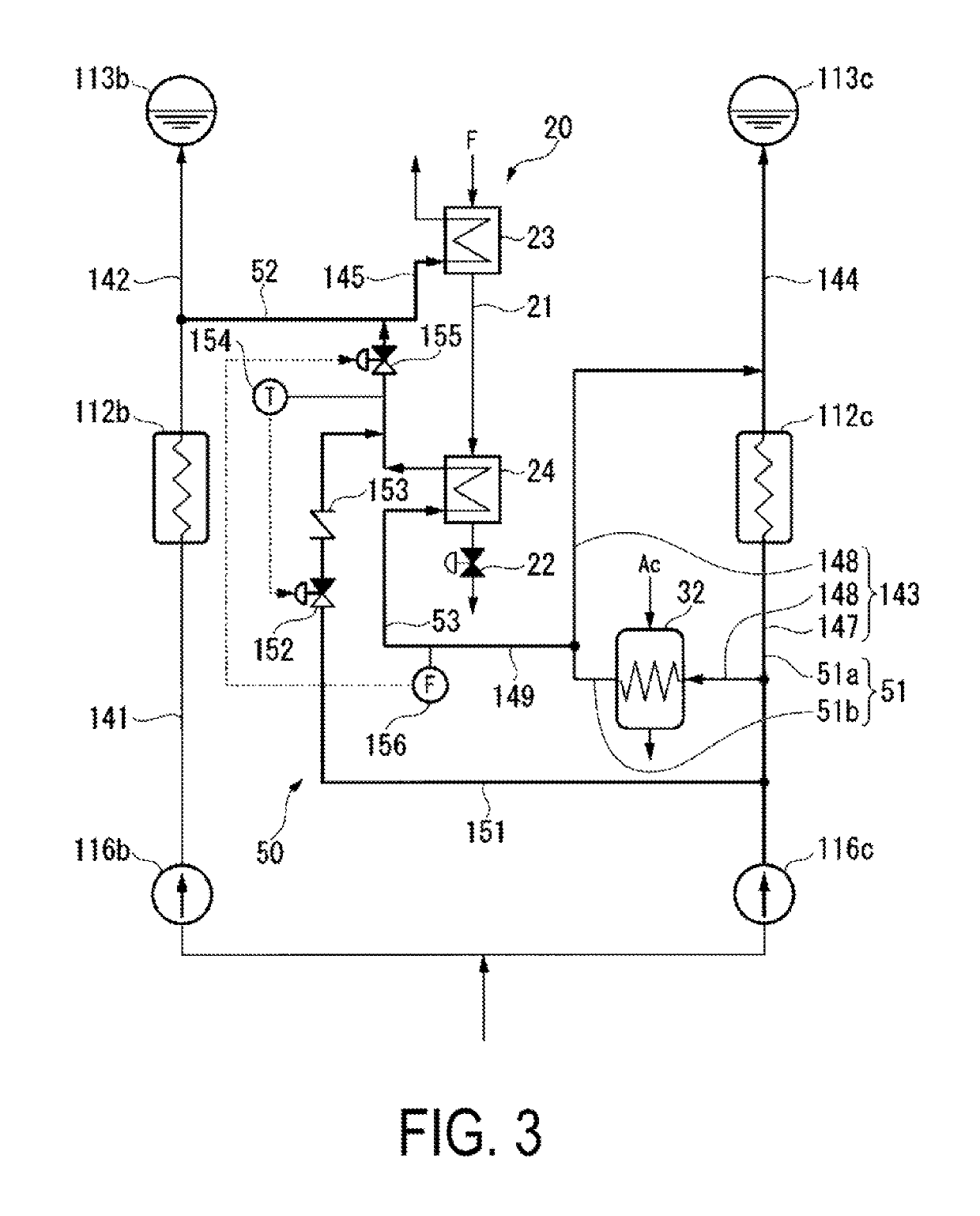
[0138]In the water feeding system 50 of the above-described embodiments, the cooling water injecting line 151 is connected to the first feed water main line 51a at the position located further to the high-pressure pump 116c side than the branching position of the first feed water div...


PUM


Abstract

A water feeding system provided with: a first feed water line through which first feed water flows; a second feed water line through which second feed water having a lower pressure than the first feed water flows; a first heater that heats the first feed water; a first feed water introducing line that guides first heated feed water, which is the first feed water that has been heated by the first heater, to the second feed water line; a medium heat exchanger that causes the first heated feed water to exchange heat with a medium, thereby cooling the first heated feed water and heating the medium; and a cooling water injecting line that injects cooling water having a lower temperature than the first heated feed water into the first feed water introducing line, at a position located further to the second feed water line side than the medium heat exchanger.

Description

TECHNICAL FIELD[0001]The present invention relates to a water feeding method, a water feeding system that implements the water feeding method, and a steam generating facility provided with the water feeding system.[0002]This application claims priority based on JP 2015-146735 filed in Japan on Jul. 24, 2015, of which the contents are incorporated herein by reference.BACKGROUND ART[0003]A combined cycle plant includes a gas turbine, an exhaust heat recovery boiler that generates steam using the heat of exhaust gas from the gas turbine, a steam turbine that is driven by the steam from the exhaust heat recovery boiler, and a condenser that turns steam exhausted from the steam turbine back into water. Water inside the condenser is supplied to the exhaust heat recovery boiler via a feed water line.[0004]In a combined cycle plant disclosed in Patent Document 1 described below, fuel of a gas turbine is preheated using water heated in an exhaust heat recovery boiler. The exhaust heat recove...

Claims


Application Information

Patent Timeline
Patent Type & Authority Patents(United States)
IPC IPC(8): F02C7/224F01K23/06F01K23/10F01K7/38F22D1/14F22B1/18F22D1/12
CPCF02C7/224F01K7/38F01K23/06F22B1/18F22D1/12F22D1/14F01K23/10F01K23/106Y02E20/16F02C6/18F02C7/141F02C9/28
Inventor SUMIMURA, NAOHIROYAMASAKI, MASAAKIMURAKAMI, MASAYUKI
Owner MITSUBISHI POWER LTD
Why Eureka
Try Eureka