
Advanced aerodynamic projectile and method of making same

a technology of aerodynamic projectiles and projectiles, which is applied in the direction of projectiles, weapons, ammunition projectiles, etc., can solve the problems of lead-based bullets, inhumane killing or wounded animals in hunting scenarios, and significant copper fouling in the barrels, so as to improve the design of bullets

Active Publication Date: 2019-07-16
BADLANDS PRECISION LLC
View PDF49 Cites 4 Cited by
  • Summary
  • Abstract
  • Description
  • Claims
  • Application Information

AI Technical Summary

Benefits of technology

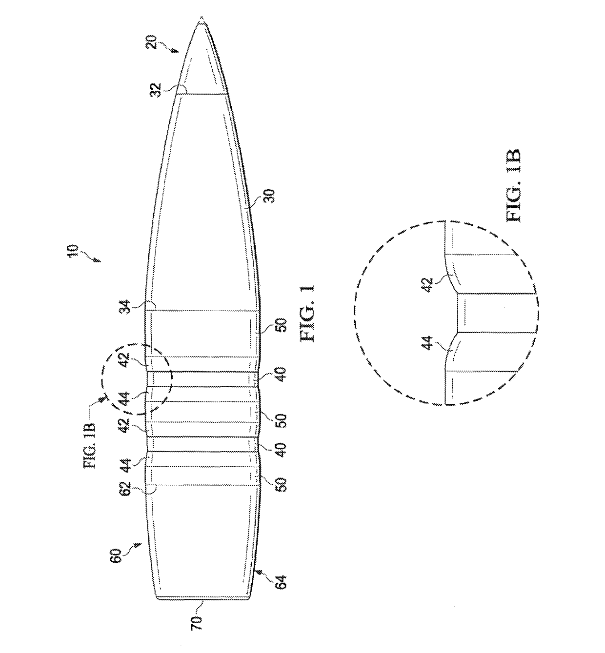
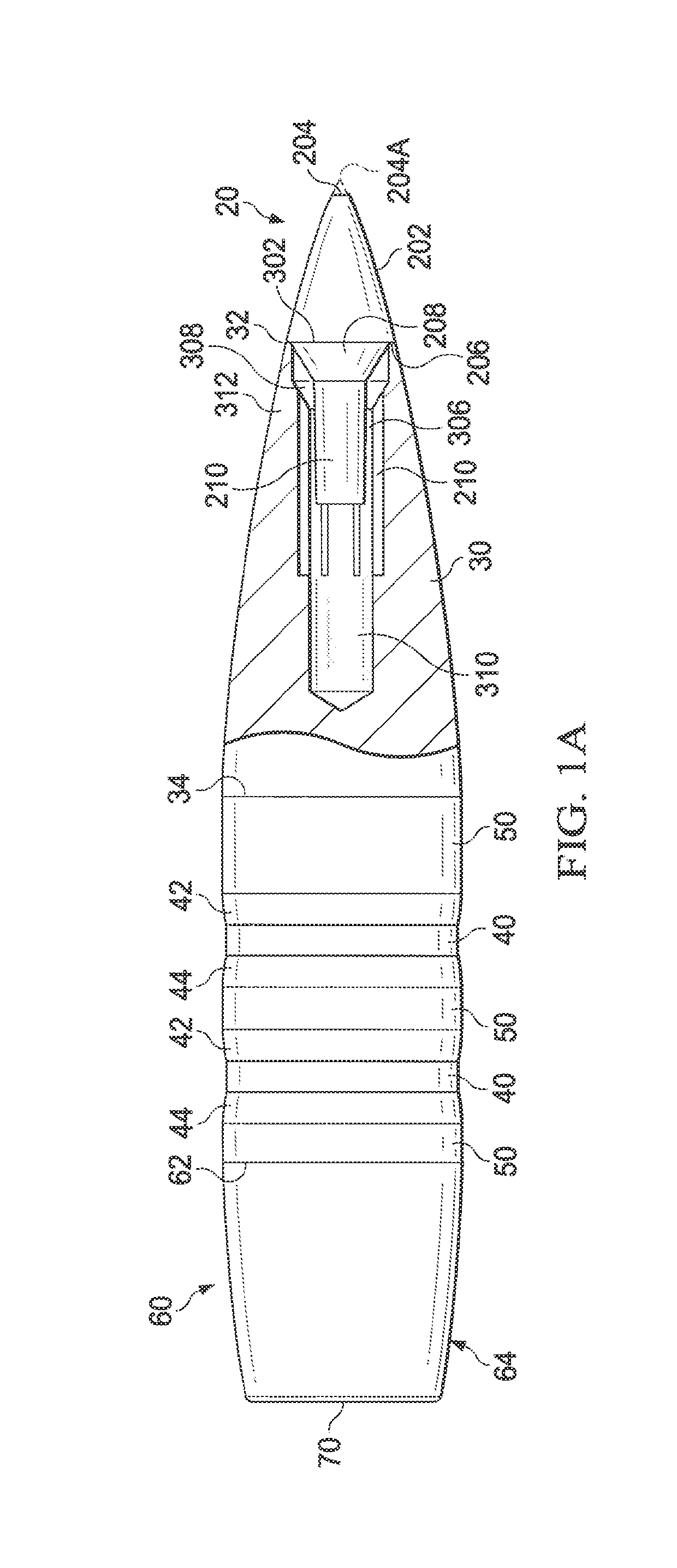
The patent text describes an improved design for a bullet. The bullet is made from a copper or metal alloy and has grooves on its bearing surface. It also has a curved tip and a shaping of the grooves that resembles an ogive or parabola. The technical effect of this design is a more efficient and accurate bullet that can be easily ejected from a firearm.

Problems solved by technology

One disadvantage of cup and core bullets is that a swaged cup and core bullet has been shown to separate upon impact, causing the possibility of an inhumane kill or a wounded animal in a hunting scenario.
While these technologies represented improvements over traditional cast, swaged, and cup and core designs, the bullets were still lead-based, which is a toxic metal.
However, because of the hardness of the bullet as a whole, the bullet can create significant copper fouling in the barrel because of the reduced malleability or deformability of the solid copper bullet.
The displaced copper / gilding metal is then deposited within the barrel, resulting in loss of accuracy by disturbing the uniformity of the rifling and preventing the consistent travel of a projectile through the barrel.
As most bullets are traveling over the speed of sound, and some at hypersonic speeds (over Mach 3), the turbulence created by the transverse grooves in the bearing surface create additional shock waves, causing turbulence, substantially increasing drag, and reducing the range that the bullet velocity will remain supersonic.
As the bullet reaches approaches subsonic velocity a velocity zone is reached, known as the transonic zone, wherein there bullet can become unstable because of boundary layer separation of the air passing over the rear of the bullet.
This destabilization can cause the bullet to deviate from its supersonic trajectory, which in turn has a detrimental effect on accuracy.
While these polymer tips work to some degree, they also have a tendency to impede expansion of the bullet upon impact, and in any event do nothing to reduce the drag created by the transverse grooves.
However, the hollow-point design creates additional unwanted nose drag during flight.
However, the degree of expansion attributable to the plastic tip design is negligible.

Method used


Image

  • Advanced aerodynamic projectile and method of making same
  • Advanced aerodynamic projectile and method of making same
  • Advanced aerodynamic projectile and method of making same

Examples


Embodiment Construction

[0015]In accordance with embodiments of the invention, a machined stock of copper, copper alloy, or other suitable materials for use as rifle projectiles, are manufactured to reduce drag and increase the ballistic coefficient of the projectile. Additionally, the projectiles are designed to achieve greater muzzle velocity through reduced bearing surface and reduce fouling in a steel or chrome-lined barrel.

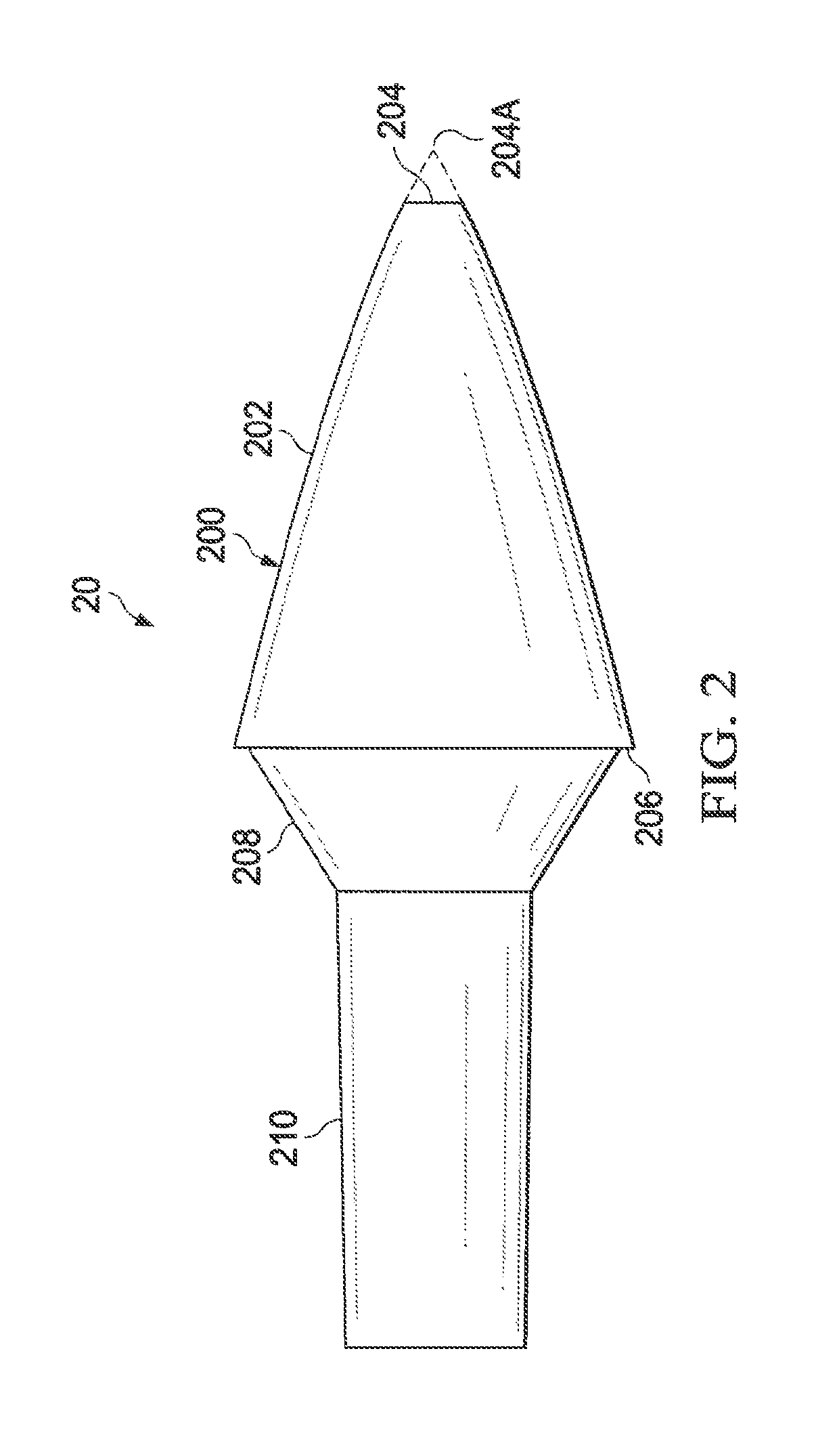
[0016]FIGS. 1 & 1A show an embodiment of the present invention. Projectile 10 shows a tip 20, a nose 30, grooves 40, bearing surfaces 50, tail portion 60, and base 70. Although not necessary, in a preferred embodiment, the projectile is machined of a uniform material, such as copper or copper alloy. The nose portion 30 includes a meplat 32 and a nose transition 34 where the nose meets the bearing surface. The shape of nose 30 is typically an ogive, which reduces the coefficient of drag of the projectile 10 and increases the ballistic coefficient. Because of the supersonic, and somet...


PUM


Abstract

A projectile is improved aerodynamically by cutting grooves having parabolic transitions between the depth of the groove and the bearing surface. An ejectable tip is attached to the leading edge of the projectile to facilitate greater ballistic coefficient during flight and improved expansion upon impact at a soft target.

Description

BACKGROUND OF THE INVENTION1. Field of the Invention[0001]This invention is directed to projectiles designed and manufactured for use in metallic cartridges for use in a firearm. The design of modern rifle cartridges has remained largely unchanged for over a century. A metallic casing designed to fit in a specified chamber of a firearm has a base with a primer pocket, a cavity, a mouth, and a projectile (bullet) seated in the mouth of the case. As will be shown below, the bullet may sometimes be “crimped” by the case mouth to ensure a tighter and more consistent fit of the bullet within the case mouth.[0002]The primer pocket is sized to accept a metallic primer containing a primary explosive that ignites when struck by a firing pin of the firearm, causing sufficient heat and pressure to ignite incendiary powder disposed within the cavity of the metallic cartridge. The ignition of the powder creates pressure within the case that propels the bullet from the mouth of the case, through ...

Claims


Application Information

Patent Timeline
Patent Type & Authority Patents(United States)
IPC IPC(8): F42B10/42F42B14/02F42B33/00F42B12/74F42B12/34F42B30/02
CPCF42B12/34F42B10/42F42B33/00F42B14/02F42B30/02F42B12/74
Inventor FOURNIER, GEORGE RICHARDSEJNOHA, JASON M.
Owner BADLANDS PRECISION LLC
Learn More