Investment casting

a technology of investment casting and component casting, applied in the field of investment casting, can solve the problems of difficult or uneconomic manufacturing, difficult control of both of these aspects, and difficult to get accurate measurement data of this without destroying the mould, and achieve the effect of controlling cooling

Active Publication Date: 2019-07-23
ROLLS ROYCE PLC
View PDF5 Cites 0 Cited by
  • Summary
  • Abstract
  • Description
  • Claims
  • Application Information

AI Technical Summary

Benefits of technology

[0019]It will be appreciated that the method enables provision of a full 3D representation of shell thickness for each individual mould in a non-destructive manner. This dimensional data can be used to improve and optimize the shelling process, facilitating the development of shell moulds which result in optimized heat loss and thermal conditions for producing a directionally solidified component. Product quality can thus be improved and better controlled, and scrap rates can be reduced.

Problems solved by technology

It is known to use casting to produce a wide range of components with complex shapes that would be otherwise difficult or uneconomical to manufacture by other methods.
Both of these aspects are difficult to control.
In the case of the mould thickness, it is very difficult to get accurate measurement data of this without destroying the mould.
It is difficult to get data on this maximum plan view profile of the moulds to generate an optimum baffle profile.
Hence, the baffle is typically designed with a larger gap than might actually be needed resulting in below optimal cooling and consequent metallurgical scrap rates which can be more than 15% of throughput.

Method used


Image

  • Investment casting
  • Investment casting
  • Investment casting

Examples


Embodiment Construction

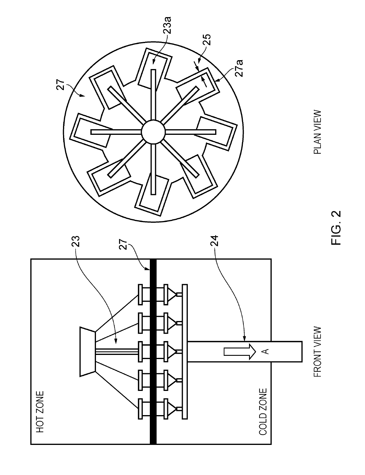
[0027]As can be seen in FIG. 2, a directional solidification apparatus comprises an array 23 of previously manufactured shell moulds 23a arranged circumferentially and equally spaced from each other. The array can be drawn in the direction A by means of a ram 24. A baffle 27 defines a barrier between a hot zone (at the top of the front view) and a cold zone (at the bottom of the front view). As can be seen from the plan view the baffle has a profile made up of individual profile segments 27a which are each consistent with a substantial portion of a perimeter of the shell moulds 23a allowing an offset clearance 25 which facilitates clear passage of the array of shell moulds 23 as they move in the direction A in a directional solidification process.

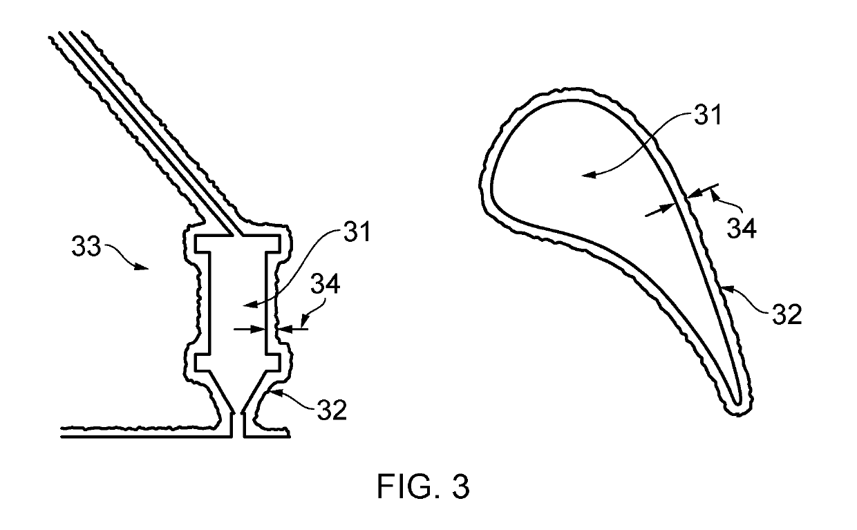
[0028]As can be seen a shell mould 33 has a cavity 31 bounded by a wall 32. The wall has a thickness 34 which, as can be seen, is variable across the wall 32. In the Figure shown, the shell mould 33 is shaped to cast an aerofoil shape, for ...


PUM

PropertyMeasurementUnit
dimensionsaaaaaaaaaa
radiusaaaaaaaaaa
thicknessaaaaaaaaaa

Abstract

A method for designing a baffle including using patterns to produce an array of shell moulds, generating a 3-D image of the outer surface of each shell mould in the array of shell moulds, stacking the individual 3-D images for a plurality of the shell moulds to produce a conglomerate shell mould profile, determining a maximum cross sectional area of the conglomerate shell mould profile in a plane orthogonal to a direction along which the shell moulds are to be drawn through the baffle, defining a baffle profile segment which is consistent with a substantial portion of the conglomerate shell mould profile at the maximum cross sectional area, scaling the baffle profile segment to provide an offset clearance between the baffle profile segment and the maximum cross sectional area of the conglomerate shell mould profile, and reproducing the baffle profile segment to provide an array of baffle profile segments.

Description

FIELD OF THE INVENTION[0001]The present invention relates to component casting and more particularly but not exclusively to component casting involving directional solidification of single crystal components for engines, such as blades, seal segments and nozzle guide vanes.BACKGROUND TO THE INVENTION[0002]It is known to use casting to produce a wide range of components with complex shapes that would be otherwise difficult or uneconomical to manufacture by other methods. Molten material is poured into a mould which defines the shape of the component. The material is then allowed to cool and solidify in the shape of the mould. Where the material has a melting point well above standard ambient temperature and pressure (SATP) (which is typical for most metals), the pouring of the molten material takes place within a furnace. It is known to control the cooling of the molten material in the mould to control the microstructure of the solidified material.[0003]It is known to provide multipl...

Claims


Application Information

Patent Timeline
Patent Type & Authority Patents(United States)
IPC IPC(8): B22D27/04B22C9/04B22C7/02B22C19/04C30B29/52C30B11/00B01F3/04
CPCB22D27/045B22C7/02B22C9/04C30B11/00C30B29/52B22C19/04F05D2240/126B01F2003/04134C30B11/002B01F23/231121
Inventor TORPEY, JOHN S.DURRANT, GEORGEFREEMAN, FELICITY
Owner ROLLS ROYCE PLC
Why Eureka
Try Eureka