Radiofrequency filter with improved attenuation of common mode signals

a radio frequency filter and common mode technology, applied in the field of radiofrequency filters, can solve the problems of not being able to filter out the data of interfering signals, the inability to electronically connect to the device inside the chamber without allowing stray rf signals to interfere, etc., to achieve a wide range of band operation, reduce negative effects on data signals, and increase the attenuation

Active Publication Date: 2019-08-06
RAMSEY JOHN GORDON
View PDF7 Cites 2 Cited by
  • Summary
  • Abstract
  • Description
  • Claims
  • Application Information

AI Technical Summary

Benefits of technology

[0007]A radiofrequency filter is provided that comprises a novel common mode choke arrangement that is used as both a traditional common mode choke as well as the inductance in a low pass filter. The inductance in the current path is used in a low pass filter configuration to present an even higher attenuation to common mode currents. The low pass filter is capacitively configured to reduce negative effects on data signals while still being effective at filtering. Multiple chokes and in some embodiments differing core materials for the chokes provide for wider band operation without pronounced resonances.

Problems solved by technology

The need for such filters is readily apparent when a device is being tested in an environment where there may be other RF signals which are not part of the test and their radiation may disturb the test or influence measurements.
A shielded test enclosure chamber provides a nearly ‘sterile’ RF environment in which to test a device, but the problem of how to electronically connect to the device inside the chamber without allowing stray RF signals to interfere is an issue.
In these cases, there is no way to filter out the data from the interfering signals as they both fall within the same general frequency range.

Method used


Image

  • Radiofrequency filter with improved attenuation of common mode signals
  • Radiofrequency filter with improved attenuation of common mode signals
  • Radiofrequency filter with improved attenuation of common mode signals

Examples


Embodiment Construction

[0038]For a general understanding of the present invention, reference is made to the drawings. In the drawings, like reference numerals have been used throughout to designate identical elements.

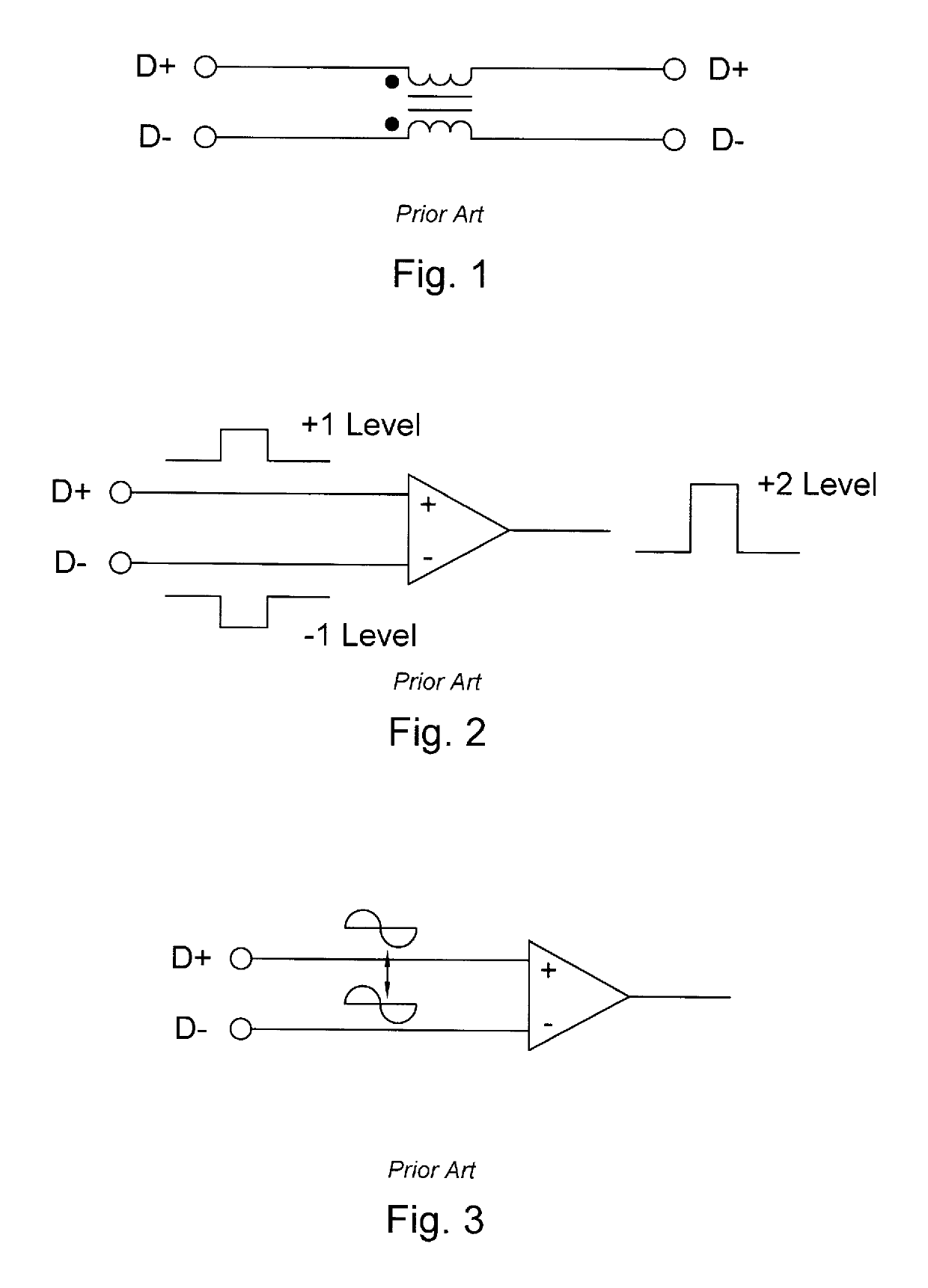
[0039]FIG. 1 shows use of a conventional common-mode choke on data signal lines. The choke has two windings, each closely coupled and wound on a magnetic core, such a winding is usually called a Bifilar winding, indicating its balanced nature. Such core material may be iron, ferrite or other such material. It is noted that different core materials may have certain advantages at various frequencies, currents and other factors. In the embodiment of this invention, core material is selected mainly in conjunction with frequency of operation. Further, in this example provided, attenuation is −6 db. / octave.

[0040]FIG. 2 shows the basics of conventional Differential Signaling. Differential signaling is a method for electrically transmitting information using two complementary signals. The technique s...


PUM


Abstract

A radiofrequency filter utilizing a common mode choke both as a traditional common mode choke as well as the inductance in a low pass filter. Filter topology as well as component selection is optimized for wide band operation. Common mode chokes allow differential currents to pass with little attenuation while common mode currents are effectively presented with an inductance in the common current path. This inductance is used in a low pass filter configuration to present an even higher attenuation to common mode currents. The use of multiple chokes and / or differing core materials contributes to wider band operation without pronounced resonances. The capacitance used in the low pass filter is connected in a way as to reduce its effect on the data signals while still being effective in filtering.

Description

CROSS-REFERENCE TO RELATED PATENT APPLICATIONS[0001]This application claims priority to U.S. Patent Application Ser. No. 62 / 408,467 filed Oct. 14, 2016 entitled “Radiofrequency Filter With Improved Attenuation of Common Mode Signals” by John Gordon Ramsey, the entire disclosure of which is incorporated herein by reference.BACKGROUND OF THE INVENTION1. Field of the Invention[0002]The present invention relates to radiofrequency filters, and more particularly, relates to a radio frequency filter with improved attenuation of common mode signals.2. Description of Related Art[0003]The present invention relates to radiofrequency (RF) filters for data signal lines, particularly high speed differential data signaling such as used in USB3 and HDMI devices. In one example, the present invention is used in RF filtering of interface cables used when connecting to wireless devices being tested in a shielded RF test enclosure. A typical RF shielded test enclosure is described in U.S. Pat. No. 5,59...

Claims


Application Information

Patent Timeline
Patent Type & Authority Patents(United States)
IPC IPC(8): H03H7/42H01R13/659H01P1/22H03H7/09H03H7/00H05K9/00H04B15/02H03H1/00H01P1/207
CPCH03H7/427H01P1/225H01R13/659H03H7/00H05K9/0066H05K9/0069H03H7/09H04B15/02H01P1/207H03H1/0007
Inventor RAMSEY, JOHN GORDON
Owner RAMSEY JOHN GORDON
Why Eureka
Try Eureka