Backplane electronic board and associated electronic control unit

a backplane electronic board and electronic control unit technology, applied in the field of electronic computers, can solve the problems of high frequency reflection phenomena, excessive price cost, and poor performance of electromagnetic compatibility, and achieve the effect of increasing the length of the electronic board and reducing the connection spa

Active Publication Date: 2019-08-06
SAFRAN ELECTRONICS & DEFENSE
View PDF8 Cites 3 Cited by
  • Summary
  • Abstract
  • Description
  • Claims
  • Application Information

AI Technical Summary

Benefits of technology

[0018]The invention gives the possibility of suppressing the entirety of the wire cablings and ribbon cables in the rear block.
[0019]The invention further gives the possibility of suppressing all the components directly mounted on the mechanical frame as well as all the additional boards (other than the electronic boards).
[0020]The invention gives the possibility of reducing the connection space between the external connector and the electronic boards. The depth of the computers being set in the avionics, this also practically gives the possibility of increasing the length of the electronic boards.
[0021]The invention also gives the possibility of allocating filtering functions on the main printed circuit of the bottom block notably which allows the suppression of the additional boards and filters.

Problems solved by technology

The wrapping technique has many drawbacks and notably an excessive price cost, the obsolescence of the components and of the skills and poor performances of electromagnetic compatibility.
Another drawback of wrapping is the absence of impedance matching and the noise may generate reflection phenomena at high frequencies and electronic failures on the critical signals.
Another drawback of wrapping is that it requires a cabling area with a consequent width which is a penalty to the compactness of the computer 1.
All these solutions are complex, expensive and cumbersome.
Now, in such electronic boards, the resin risks moving upwards in the blind holes during the assembly of the printed circuits, which has the consequence that the connection elements in the form of pins can no longer be inserted into the blind holes.

Method used


Image

  • Backplane electronic board and associated electronic control unit
  • Backplane electronic board and associated electronic control unit
  • Backplane electronic board and associated electronic control unit

Examples


Embodiment Construction

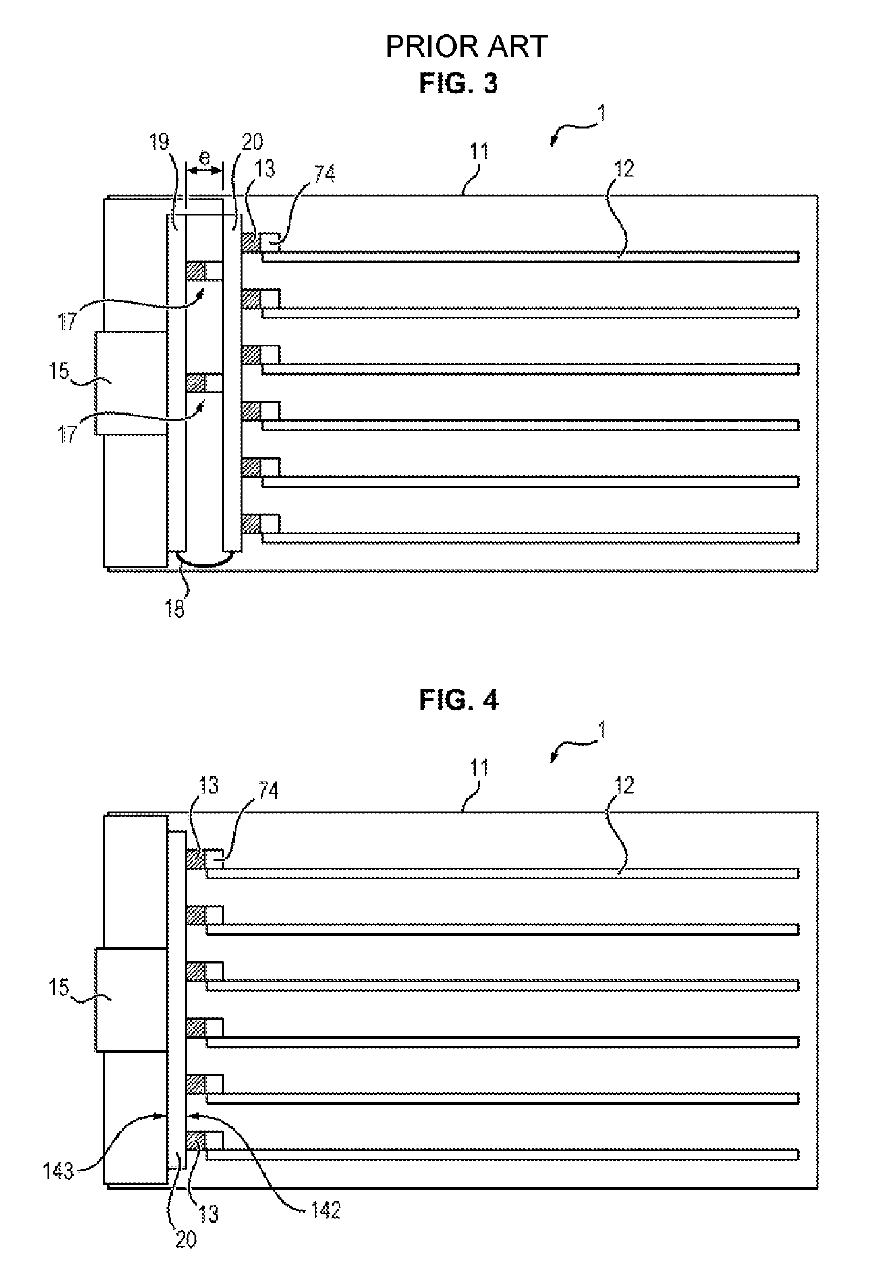
[0044]With reference to FIG. 4, an electronic computer 1 includes a mechanical frame 11, one or several electronic boards 12 mechanically maintained in the frame 11 and a so called ‘backplane’ electronic board 20 or ‘backplane’ which forms the bottom of the mechanical frame 11.

[0045]Mechanical Frame 11

[0046]With reference to FIG. 4, the mechanical frame 11 is typically a rectangular parallelepiped including two open parallel faces' a first open face adapted for introducing electronic boards 12 and a second open face adapted so as to be closed by the ‘backplane’ board 20. The electronic boards 12 are mechanically maintained in the frame 11 for example with rails.

[0047]With reference to FIGS. 6 and 7, the backplane board 20 (FIG. 4) is formed with a main circuit 28 for which the dimensions correspond to the open face of the bottom block. The backplane board 20 is attached through its periphery on the flanks of the mechanical frame 11. With reference to FIG. 10, the computer may also i...


PUM


Abstract

The present invention concerns a backplane electronic board (20) having on inner face (142) suitable for being connected to electronic board connectors (12) and an outer face (143) suitable for being connected to an outer connector (15), the backplane board (20) being characterized in that it has blind holes opening on the inner face (142) of same, and holes opening on the outer face (143) of same, the holes being suitable for receiving press-fit connection elements and forming therewith an electrical connection point.

Description

FIELD OF THE INVENTION[0001]The field of the invention is that of electronic computers and in particular computers of aircraft systems embedded onboard.STATE OF THE ART[0002]In modern aircrafts, it is known how to connect between them the modules for piloting and / or controlling functional members of the aircraft through one or several main buses of the aircraft. These buses are currently buses specific to the field of aviation, and notably buses using distributed serial bus protocols of the ARINC 429 types or other ones. Thus, as an example, for handling mobile elements of the landing gear of an aircraft, several piloting and / or control modules are applied, the latter being each connected to the main buses of the aircraft.[0003]Each piloting module includes a computer 1 applying a program adapted to ensure the piloting function to which it is dedicated, as well as a communication interface adapted to the main bus protocol allowing exchange of data between the computer and the main b...

Claims


Application Information

Patent Timeline
Patent Type & Authority Patents(United States)
IPC IPC(8): H05K7/14H05K3/46H01R12/70H01R12/71H05K3/00H05K1/11G06F1/18H05K3/42
CPCH05K7/1439H01R12/7064H01R12/716H05K1/111H05K1/115H05K3/0011H05K3/421H05K3/4644H05K7/1412H05K7/1445H05K7/1452H05K7/1459G06F1/184H05K2201/10295H05K3/0094H05K2201/0104H05K2201/09509H05K2201/09545H05K2201/10189
Inventor GUILLOT, FRANCOISSPOOR, PASCALCHETANNEAU, PATRICE
Owner SAFRAN ELECTRONICS & DEFENSE
Why Eureka
Try Eureka