System and method for analysis of the upper airway and a respiratory pressure support system

a technology of respiratory pressure support system and analysis system, which is applied in the field of upper airway analysis, can solve the problems of lowering the compliance of patients to use the system, change of resistance, and inability of existing pap systems to measure neither the respiration drive nor the airway resistance, so as to reduce the effect of obstruction

Active Publication Date: 2019-08-13
KONINKLJIJKE PHILIPS NV
View PDF41 Cites 3 Cited by
  • Summary
  • Abstract
  • Description
  • Claims
  • Application Information

AI Technical Summary

Benefits of technology

[0023]The system can detect airway narrowing, and this can be used as diagnostic information. The system can be arranged also to detect the location of an obstruction and optionally also the extent of airway narrowing. In this way, it becomes possible to localize the level of the airway that is narrowing, and optionally also to monitor how the narrowing develops. The airway characteristics are manifested as changes in the signals captured by the sensors. By using at least two sensors, the dynamic properties of the upper airway and the dynamics in the respiratory airflow can be resolved, based on any sound travelling past the sensors. This avoids the need for a specific sound source, so that sound sources external to the analysis system are used. The acoustic sensors are used to detect those external sounds, which may comprise noises generated by the user, ambient sounds, or noises generated by parts of a patient treatement system (such as a pump). The system can be part of a stand-alone diagnostic device, or it can be integrated into a treatment device, such as a PAP system or a flow meter or a Spirometer.
[0028]The system can be made less obtrusive by avoiding the need for a noise source in the direct vicinity of the users head. The two or more sensors are instead used to measure existing ambient noise, and from this derive the input acoustic impedance of the respiratory tract continuously, from which it can determined if (partial) collapses occur during for example during the night.
[0029]The system can however also be used with a sound source to provide a desired frequency spectrum for analysis. The use of a sound source in addition to ambient sounds means the sound source intensity can be reduced, while still ensuring a minimum signal intensity across a desired range of frequencies. This option can be provided as an additional mode of operation of the device, in addition to a mode of operation which does not make use of a dedicated sound source.
[0032]The passageway preferably comprises a tube, which can be straight, curved as well as flexible. In the case of a flexible tube, it can be coiled or otherwise bent to minimise the obstruction caused. However, shape features other than a tube can be used to induce a flow stream. For example the shaping of a mask with differently positioned sensors can enable sufficient information to be resolved.

Problems solved by technology

In the case of a central hypopnea a pressure increase will not increase the airflow, it might be even contra indicative; an unneeded pressure increase may lead to discomfort, lowering compliance of the patient to use the system.
Existing PAP systems are not able to measure either the respiration drive nor the airway resistance.
Such an analysis in the frequency domain can only determine the overall resistance of the lung, the larynx and the upper airway but does not provide the spatial information in the time domain to localize the segment in the upper airway, which causes a change of the resistance.
Thus, there is a first problem that current PAP systems cannot determine whether a hypopnea is caused by upper airway narrowing or by a reduction of respiratory drive.
Some patients adapt poorly to PAP treatment because of its obtrusive properties.
The pathophysiology of OSA is complex as it often results from an interplay of anatomical and neuromuscular dysfunctions.
Although many treatment alternatives have higher patient acceptance, they only treat a specific level of the upper airway.
This makes the applicability of these alternatives restricted to OSA sub-populations.
There is thus a second problem that airway analysis and diagnosis systems, such as used to enable suitable non-PAP treatments to be selected, can be obtrusive in their measurement techniques, mainly because they are not suitable during normal sleep.
For example it is not desirable to create sound which disturbs the user, and the system needs to be minimally obtrusive to the user.

Method used


Image

  • System and method for analysis of the upper airway and a respiratory pressure support system
  • System and method for analysis of the upper airway and a respiratory pressure support system
  • System and method for analysis of the upper airway and a respiratory pressure support system

Examples


Embodiment Construction

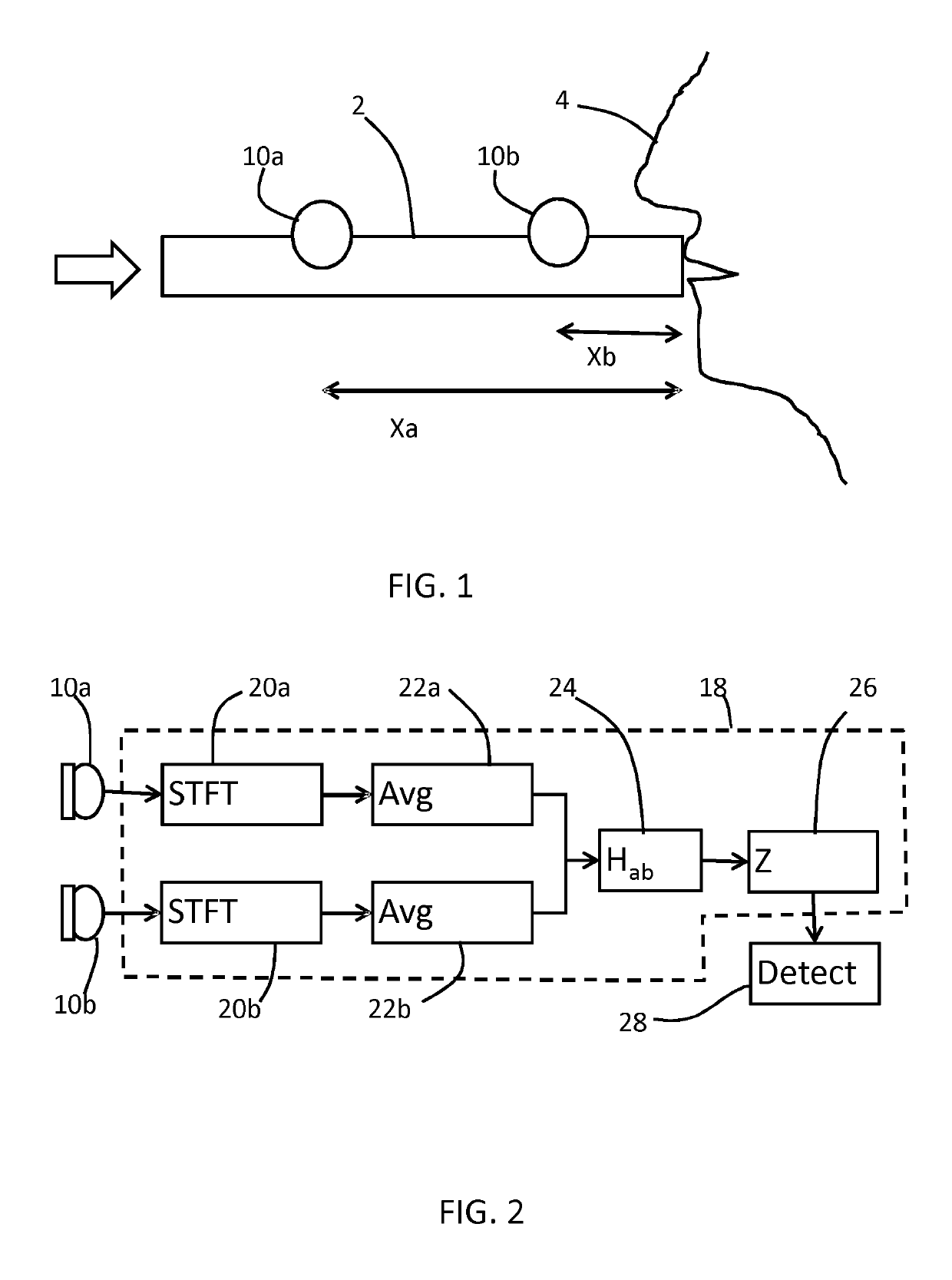
[0052]Embodiments provide a system for analysis of the upper airway in which at least two sensors are provided along a flow path leading to the mouth and / or nose of a user. A relation is derived between the two sensor signals, and this is interpreted to detect at least the presence of upper airway obstructions, and preferably also the location and / or extent of such obstructions.

[0053]Examples can be used solely as diagnostic tools and other examples can be used to assist in the control of a PAP system.

[0054]A first example will be described for diagnostic purposes.

[0055]FIG. 1 shows the general configuration.

[0056]This example makes use of a passageway 2 in the form of a tube which is provided with one end terminating at the mouth and / or nose of a user 4. The example shows the passageway leading to the user's mouth. The one end is sealed around the mouth (and / or nose) although this is not shown in FIG. 1.

[0057]A first acoustic sensor 10a is positioned at a first location along the p...


PUM


Abstract

A system for analysis of the upper airway has at least two sensors are provided along a flow path leading to the mouth and / or nose of a user. A relation is derived between the two sensor signals, and this is interpreted to detect at least the presence of upper airway obstructions, and preferably also the location and / or extent of such obstructions.

Description

CROSS-REFERENCE TO PRIOR APPLICATIONS[0001]This application is the U.S. National Phase application under 35 U.S.C. § 371 of International Application Serial No. PCT / EP2015 / 050838, filed on Jan. 19, 2015, which claims the benefit of European Serial No. 14152609.5, filed on Jan. 27, 2014. These applications are hereby incorporated by reference herein.FIELD OF THE INVENTION[0002]The invention relates to analysis of the upper airway. In particular it relates to upper airway analysis to enable positive airway pressure (PAP) treatment to be suitably controlled or to enable a suitable alternative treatment to be selected.BACKGROUND OF THE INVENTION[0003]Obstructive Sleep Apnea (OSA) is a high-prevalence disease, especially in the male adult population. OSA is very effectively treated by the application of Positive Airway Pressure (PAP). This involves the patient wearing a mask at night, which delivers pressurized air to the patient during sleep.[0004]For an optimal pressure titration an Au...

Claims


Application Information

Patent Timeline
Patent Type & Authority Patents(United States)
IPC IPC(8): A61B5/085A61B5/097A61M16/08A61B5/107A61B5/08A61B5/00A61M16/06
CPCA61B5/7282A61B5/0826A61B5/097A61B5/1072A61B5/4818A61B5/4836A61B5/7203A61B5/7257A61M16/0666A61M16/0683A61M16/0816A61M16/0875A61B5/085A61M2230/40A61B2562/0204A61M2230/005
Inventor AARTS, RONALDUS MARIAKAHLERT, JOACHIMVAN BRUGGEN, MICHEL PAUL BARBARAOUWELTJES, OKKE
Owner KONINKLJIJKE PHILIPS NV
Why Eureka
Try Eureka