
Misfire detecting apparatus for internal combustion engine

a technology for internal combustion engines and detecting equipment, which is applied in the direction of electric control, ignition automatic control, instruments, etc., can solve the problems of deteriorating the calculation accuracy of rotation changes, speed changing components, and not taking into account ignition timing at all, etc., and achieves the effect of simple calculation

Active Publication Date: 2019-08-13
HONDA MOTOR CO LTD
View PDF32 Cites 7 Cited by
  • Summary
  • Abstract
  • Description
  • Claims
  • Application Information

AI Technical Summary

Benefits of technology

The present invention provides an apparatus for detecting misfire in an internal combustion engine. This is particularly useful when the engine's output shaft is connected to a transmission via a torsion element. By setting the timing of reference and start of integration period based on the ignition timing, the apparatus can accurately determine misfire regardless of the ignition timing. Additionally, the modified engine rotational speed parameter can be accurately calculated to determine misfire without being influenced by the torsion element. Overall, the invention improves the accuracy of misfire detection in internal combustion engines.

Problems solved by technology

Accordingly, if the calculation timing of the rotation change varies due to a change in the ignition timing, influence of the inertia speed changing component changes, which may deteriorate calculation accuracy of the rotation change.
Further, the apparatus of JP-'253 determines a misfire during the warming-up operation of the engine.
However, influence of the inertia speed changing component and the ignition timing is not taken into consideration at all.

Method used


Image

  • Misfire detecting apparatus for internal combustion engine
  • Misfire detecting apparatus for internal combustion engine
  • Misfire detecting apparatus for internal combustion engine

Examples


Embodiment Construction

[0026]Preferred embodiments of the present invention will now be described with reference to the drawings.

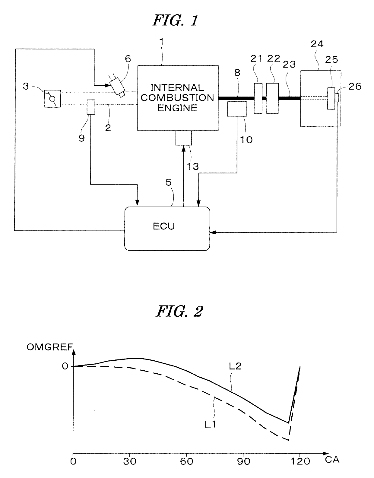
[0027]FIG. 1 is a schematic diagram of an internal combustion engine and a control system therefor according to one embodiment of the present invention. The internal combustion engine 1 (hereinafter referred to as “engine”) has six cylinders and is provided with an intake pipe 2 and an exhaust pipe 5. The intake pipe 2 is provided with a throttle valve 3.

[0028]A fuel injection valve 6 is provided for each cylinder at a position slightly upstream of an intake valve (not shown) in the intake pipe 2 and between the engine 1 and the throttle valve 3. Each fuel injection valve 6 is connected to a fuel pump (not shown) and electrically connected to an electronic control unit 20 (hereinafter referred to as “ECU 5”). A valve opening period of the fuel injection valve 6 is controlled by a control signal from the ECU 5.

[0029]An ignition plug 13 of each cylinder of the engine 1 is connecte...


PUM


Abstract

A misfire detecting apparatus for an internal combustion engine is provided. The engine has an output shaft connected via a torsion element to an input shaft of a transmission mechanism. A transmission rotational speed parameter indicative of a rotational speed of the input shaft is detected. A modified engine rotational speed parameter is calculated by modifying the detected engine rotational speed parameter based on the transmission rotational speed parameter, an engine rotation moment on the input side of the torsion element, and a transmission rotation moment on the output side of the torsion element. An average change amount of the modified rotational speed parameter, and an inertia speed changing component, are calculated. Further, a corrected rotational speed parameter is calculated by correcting the modified rotational speed parameter according to the average change amount and the inertia speed changing component. A relative speed parameter is calculated based on the corrected rotational speed parameter, and a determination parameter is calculated by integrating the relative speed parameter. The misfire determination is performed based on the determination parameter.

Description

BACKGROUND OF THE INVENTION[0001]Field of the Invention[0002]The present invention relates to a misfire detecting apparatus for an internal combustion engine, and particularly to the apparatus for determining a misfire based on a rotational speed parameter indicative of a rotational speed of the engine of which the output shaft is connected via a torsion element to an input shaft of a transmission mechanism.[0003]Description of the Related Art[0004]Japanese Patent Laid-open No. 2008-57492 (JP-'492) discloses an apparatus for determining a misfire based on the rotational speed parameter indicative of a rotational speed of the engine of which the output shaft is connected via a damper (torsion element) to a power transmission mechanism. According to this apparatus, a torque component transmitted from the mechanism on the output side of the damper is calculated, a correcting speed component which affects the rotational speed of the engine output shaft is calculated according to the tor...

Claims


Application Information

Patent Timeline
Patent Type & Authority Patents(United States)
IPC IPC(8): G01M15/04F02D41/14G01M15/11F02P5/15
CPCF02D41/1498G01M15/11F02P5/1502F02D2200/1015
Inventor MINATOYA, KEISUKEIZUMIURA, ATSUSHISASAKI, TADAYOSHIKURODA, SHIGETAKASHIKAMA, MAHITO
Owner HONDA MOTOR CO LTD
Learn More