
Semiconductor devices including self-aligned active regions for planar transistor architecture

a planar transistor and active region technology, applied in the direction of semiconductors, semiconductor devices, electrical devices, etc., can solve the problems of introducing certain variability, requiring highly complex manufacturing strategies, and contributing to significant overall manufacturing costs, so as to achieve high conformal, superior control of process variations, and well-controlled layer thickness

Active Publication Date: 2019-08-27
GLOBALFOUNDRIES US INC
View PDF6 Cites 3 Cited by
  • Summary
  • Abstract
  • Description
  • Claims
  • Application Information

AI Technical Summary

Benefits of technology

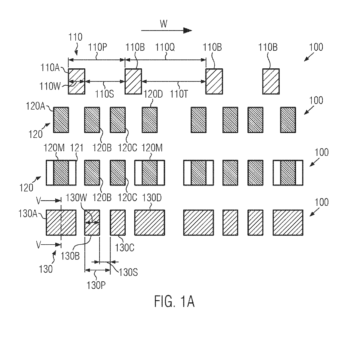
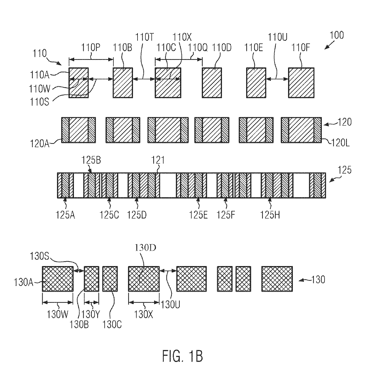
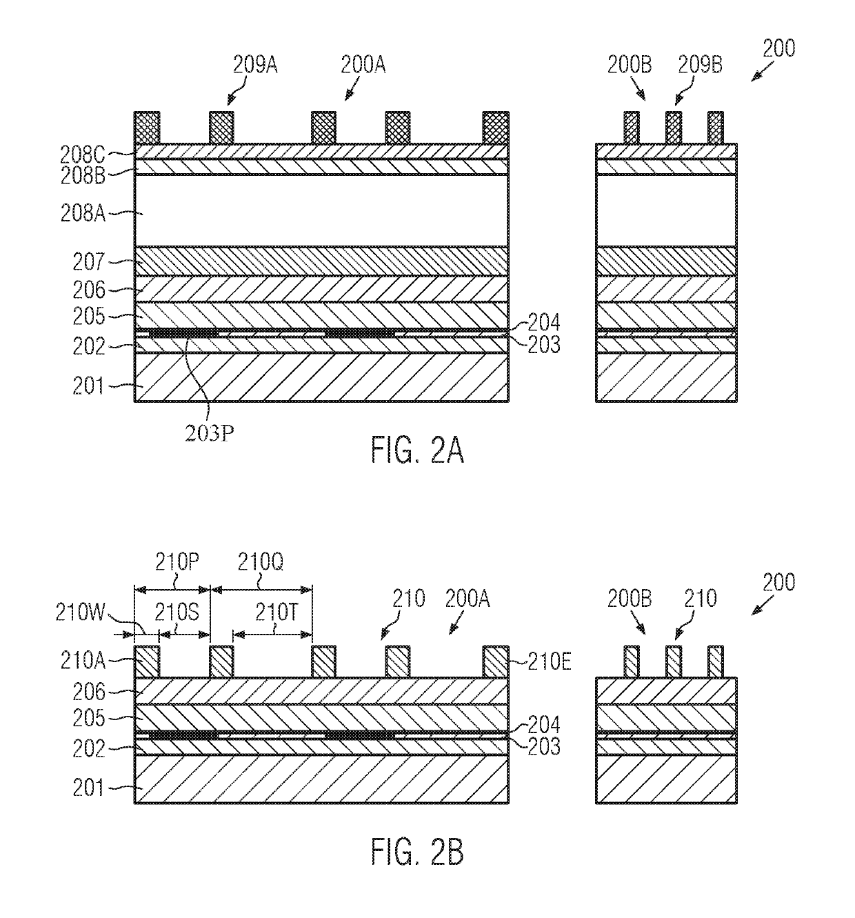
The patent aims to offer a method for achieving consistent and reliable performance in semiconductor devices by allowing for variations in device dimensions and pitches to be "replaced" by deposition-related variations, which provide superior control of process variations compared to lithography and overlay processes. Additionally, a "self-aligned" arrangement of multiple active regions of different widths and spaces can be obtained, contributing even further to superior performance and flexibility in further scaling of the device design.

Problems solved by technology

In recent developments, various approaches have been taken in order to design highly complex integrated circuits with critical dimensions of 30 nm and significantly less, wherein, on the one hand, three-dimensional transistor architectures are implemented, thereby requiring highly complex manufacturing strategies.
In particular, in densely packed device areas, such as static RAM (random access memory) areas in complex semiconductor devices, the task of providing active regions with appropriate lateral size and shape is an extremely challenging process phase, since, in this case, extremely reduced critical dimensions may also have to be implemented in order to improve device performance, for instance, in terms of overall packing density.
Consequently, a relatively large number of sophisticated lithography processes may contribute to significant overall manufacturing costs.
Moreover, in view of device performance, the various highly critical lithography processes may have to be aligned with respect to each other, thereby necessarily introducing certain variability due to unavoidable overlay errors determined by the overlay capabilities of the respective lithography processes.
This leads to a potentially dramatic variability within single cell patterning.
A corresponding process strategy to form critical device areas, such as static RAM areas, in which multiple width and pitches of active regions may have to be implemented due to respective design requirements as discussed above, may, therefore, result in reduced flexibility with respect to further scalability of respective designs, since lithography-based variations in width and pitch may have to be accounted for by the basic device design.

Method used


Image

  • Semiconductor devices including self-aligned active regions for planar transistor architecture
  • Semiconductor devices including self-aligned active regions for planar transistor architecture
  • Semiconductor devices including self-aligned active regions for planar transistor architecture

Examples


Embodiment Construction

[0026]Various illustrative embodiments of the invention are described below. In the interest of clarity, not all features of an actual implementation are described in this specification. It will of course be appreciated that in the development of any such actual embodiment, numerous implementation-specific decisions must be made to achieve the developers' specific goals, such as compliance with system-related and business-related constraints, which will vary from one implementation to another. Moreover, it will be appreciated that such a development effort might be complex and time-consuming, but would nevertheless be a routine undertaking for those of ordinary skill in the art having the benefit of this disclosure.

[0027]The following embodiments are described in sufficient detail to enable those skilled in the art to make use of the invention. It is to be understood that other embodiments would be evident, based on the present disclosure, and that system, structure, process or mech...


PUM


Abstract

Active regions for planar transistor architectures may be patterned in one lateral direction, i.e., the width direction, on the basis of a single lithography process, followed by deposition and etch processes, thereby providing multiple width dimensions and multiple spaces or pitches with reduced process variability due to the avoidance of overlay errors typically associated with conventional approaches when patterning the width dimensions and spaces on the basis of a sequence of sophisticated lithography processes. Consequently, increased packing density, enhanced performance and reduced manufacturing costs may be achieved on the basis of process techniques as disclosed herein.

Description

BACKGROUND1. Field of the Disclosure[0001]The subject matter disclosed herein relates to semiconductor devices and techniques for forming active semiconductor regions to be used for forming transistor elements based on a planar architecture.2. Description of the Related Art[0002]Integrated circuits are formed on the basis of a plurality of subsequent process steps in order to form tiny regions of precisely controlled size in one or more material layers of an appropriate substrate. These tiny regions of precisely controlled size are typically obtained by applying lithography, etch, implantation, deposition techniques and the like at various manufacturing stages in order to pattern the material layer or layers in accordance with the underlying device design.[0003]The patterning of material layers formed on the substrate material may be typically accomplished by forming a type of mask layer, which may consist of or may be formed by means of a layer of resist material that is patterned ...

Claims


Application Information

Patent Timeline
Patent Type & Authority Patents(United States)
IPC IPC(8): H01L21/027H01L27/11H01L21/033H01L21/308H10B10/00
CPCH01L21/3086H10B10/12H01L21/0337H01L21/0338H01L21/3085H01L21/3088H01L21/768H10B10/18H10B10/125
Inventor SMITH, ELLIOT JOHNCHAN, NIGELKENKARE, NILESHYOON, HONGSIK
Owner GLOBALFOUNDRIES US INC
Learn More