DC-DC converter with regulator having a plurality of parameter sets

a technology of dc-dc converter and regulator, which is applied in the direction of electric variable regulation, process and machine control, instruments, etc., can solve the problems of difficult or even impossible approval or certification, and achieve the effect of preventing the bypass of the pfc, high dynamic response, and preventing the voltage dip

Active Publication Date: 2019-09-10
ROBERT BOSCH GMBH
View PDF4 Cites 0 Cited by
  • Summary
  • Abstract
  • Description
  • Claims
  • Application Information

AI Technical Summary

Benefits of technology

[0007]Thus, if necessary (as indicated by the characteristic parameter or characteristic values) it is possible to switch from a slower parameter set to a parameter set with faster regulation behavior, in order to prevent an excessive increase or decrease in the output voltage or to counteract this more quickly. A short-term degradation in the power factor is accepted in this case. A corresponding changeover can be implemented quickly and easily. Conventional or established control concepts can each be maintained separately—in the form of a respective set of control parameters. There is no need to create a new overarching control concept, it is only necessary to change between conventional control concepts.
[0037]The invention is based on the recognition that the principle of dynamic control parameter modification can also be used in a wide variety of other applications in addition to audio amplifiers. Whenever the consumer operated by a power supply with PFC function has a high dynamic response, by using this invention the stability of the internal operating voltage can be increased. Since in most cases electronic devices are nowadays controlled by digital control units, in many cases a suitable signal indicating the power absorbed by the consumer is available, which is incorporated into the regulation of the PFC stage in an appropriate manner.

Problems solved by technology

Depending on the relevant standard, this may make approval or certification more difficult or even impossible.

Method used


Image

  • DC-DC converter with regulator having a plurality of parameter sets

Examples


Embodiment Construction

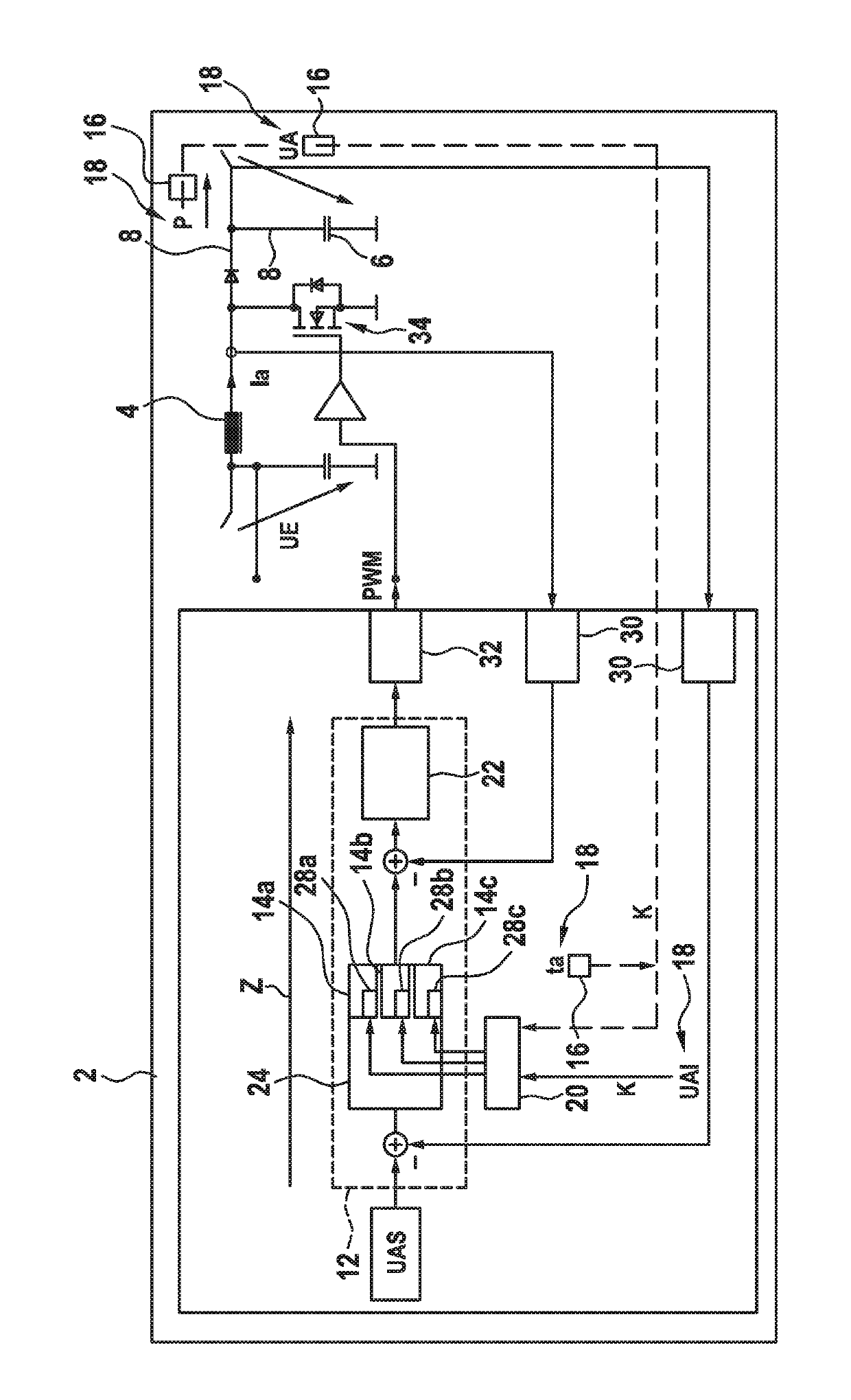
[0041]FIG. 1 shows a converter 2 in the form of a CCM Average Current Mode Boost Converter.

[0042]The converter 2 is used to convert a DC input voltage UE into a DC output voltage UA. The converter 2 contains an inductance 4 and a capacitance 6, which are interconnected in a power-conducting path 8.

[0043]The converter 2 contains a regulator 12 for regulating the current voltage value of the output voltage UA to a target value UAS. The regulator 12 contains a set of parameters 14a which currently determines its regulation behavior. The parameter set 14a is therefore currently activated in the regulator 12.

[0044]The converter 2 also contains a measurement module 16 for determining at least one characteristic value K of at least one characteristic parameter 18 of the converter 2. In the example the characteristic parameter 18 is the output voltage UA, the characteristic value K is the current voltage value UAI (actual value of UA). The measurement module 16 is therefore a voltage meter....


PUM


Abstract

A converter is provided for converting a DC input voltage (UE) into a DC output voltage (UA). The converter includes a regulator for regulating the DC output voltage (UA) to a target value (UAS), wherein the regulator comprises a parameter set that determines the regulation behavior thereof. The converter includes a measurement module for determining at least one characteristic value (K) of at least one characteristic parameter of the converter, and at least two interchangeable parameter sets for the regulator Each one of the parameter sets can be activated in the regulator, wherein a first one of the parameter sets has a slower regulation behavior with regard to the DC output voltage (UA) than a second of the parameter sets. The converter includes a control module for the exchange and activation of each of the parameter sets in the regulator depending on at least one of the characteristic parameters.

Description

BACKGROUND OF THE INVENTION[0001]Due to increasingly stringent regulatory requirements more and more electronic devices contain devices which optimize the supply current consumed in terms of the harmonics contained therein. Conventionally designed switching power supplies usually have a rectifier and a smoothing capacitor. The latter is only charged under load when the instantaneous value of the sinusoidal supply voltage rises above the DC potential of the smoothing capacitor. The consequence is only a short current pulse, which recharges the capacitor. A Fourier analysis of this current waveform usually shows numerous harmonics. Depending on the relevant standard, this may make approval or certification more difficult or even impossible.[0002]It is known from patent DE 10 2010 063 126 A1 that in order to charge the high-voltage vehicle battery of a hybrid or electric vehicle via, for example, a public mains power supply, a charging device is required. Known charging devices for hig...

Claims


Application Information

Patent Timeline
Patent Type & Authority Patents(United States)
IPC IPC(8): H02M3/156H02M1/42H02M1/00
CPCH02M3/156H02M1/4225H02M2001/0025H02M2001/0009Y02B70/10H02M1/0025H02M1/0032H02M1/0009
Inventor STEIN, THOMASHOFFMEISTER, FABIANPLAGER, JOSEF
Owner ROBERT BOSCH GMBH
Why Eureka
Try Eureka