Interferometric doppler radar and method for wave and water level measurement

a doppler radar and wave level technology, applied in the field of water monitoring equipment, can solve the problems of large maintenance costs, large cost of station construction, and relatively inaccurate non-contact equipment, and achieve the effect of maximizing measurement accuracy and resolution

Active Publication Date: 2019-10-08
UNIV OF FLORIDA RES FOUNDATION INC +1
View PDF14 Cites 0 Cited by
  • Summary
  • Abstract
  • Description
  • Claims
  • Application Information

AI Technical Summary

Benefits of technology

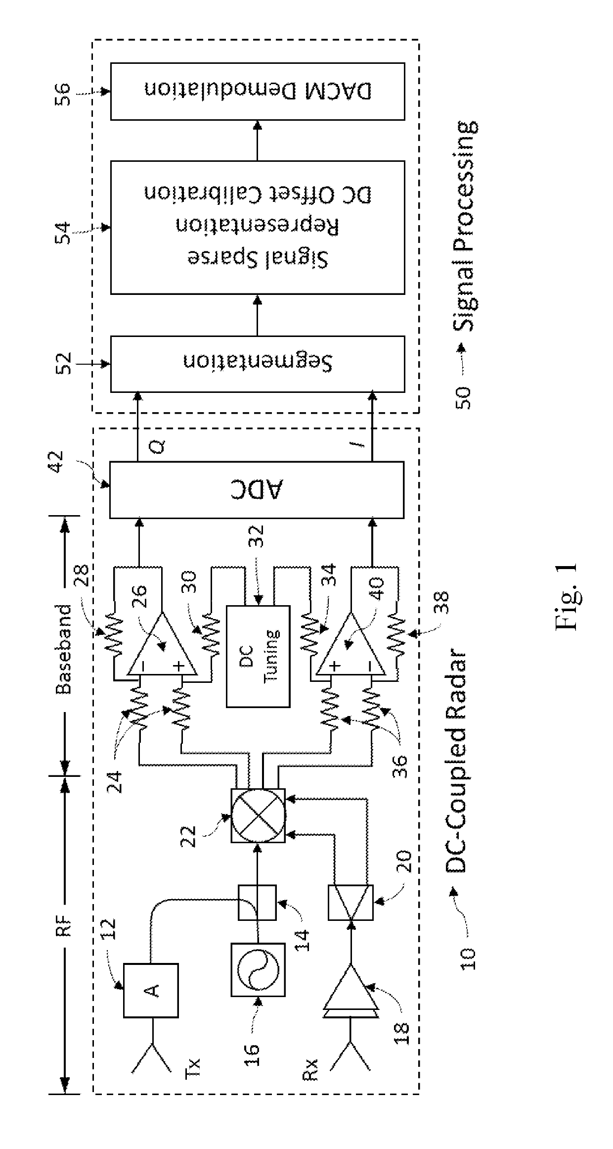
[0010]A primary objective of the present invention is to provide methods, systems and devices for a single DC-coupled CW Doppler radar that is capable of detecting water elevation changes in time for maximizing measurement accuracy and resolution.
[0011]A secondary objective of the present invention is to provide methods, systems and devices for providing a wireless and low-cost radar sensor that accurately measure water surface elevation in real time that is compact and uses low power.
[0013]A fourth objective of the present invention is to provide methods, systems and devices that accurately measure water surface elevation which can use an embedded processor, enabling data processing at a sensor location and provides wireless transmission to a computer or base station.
[0014]A fifth objective of the present invention is to provide methods, systems and devices that accurately measure water surface elevation which uses a non-contact measurement approach, eliminating any potential interference from biologic growth or anthropogenic contaminant exposure.
[0015]A sixth objective of the present invention is to provide methods, systems and devices that accurately measure water surface elevation that can group sensors to work as a network, enabling assessment of spatial variability in tidal zones and run-up regions.
[0020]An eleventh objective of the present invention is to provide methods, systems and devices for a radar gauging technique employs a DC-coupled architecture that allows accurate measurement of the slow-varying water level and is immune from the interference of multipath echoes.

Problems solved by technology

Traditional water level gauging instruments are generally in contact with the water itself (susceptible to biofouling) or include relatively expensive non-contact equipment that is relatively inaccurate when used.
It is costly to build up the station and requires a lot of permanent maintenance.
Ultrasonic has low accuracy due to its long wavelength resolution.
Laser sensors are costly and not easy to be installed for long-term gauging.
However, pulse radar is usually not desirable due to the low measurement accuracy unless an expensive data converter is used.
FMCW radar, on the other hand, suffers from multipath echoes reflected from various objects around the water body, which limits the radar resolution and is also inaccurate.
However, if the displacement is so large that it is comparable to the distance between the subject and the radar, e.g. in the case of radar water level gauging, it would significantly affect the power received at the radar input and the baseband signals would be subject to inconstant amplitude and dynamically varying DC offset.
Moreover, the large displacement inevitably leads to phase ambiguity in the conventional arctangent demodulation.
While many radar gauging devices are research projects in academic institutions, commercial businesses can include Campbell Scientific, which provides a pulse radar sensor that is subject to lower accuracy in water level displacement measurement compared to CW radar; OTT RLS Radar Level Sensor product that has low accuracy of 0.01 ft and measures water level every 20 seconds—not continuously; VAISALA is another example of a pulse radar sensor, subject to lower accuracy and higher hardware complexity. in water level displacement measurement in comparison to CW radar; and VEGAPULS which is based on ultrasonic signals.

Method used


Image

  • Interferometric doppler radar and method for wave and water level measurement
  • Interferometric doppler radar and method for wave and water level measurement
  • Interferometric doppler radar and method for wave and water level measurement

Examples


Embodiment Construction

[0051]Before explaining the disclosed embodiments of the present invention in detail it is to be understood that the invention is not limited in its applications to the details of the particular arrangements shown since the invention is capable of other embodiments. Also, the terminology used herein is for the purpose of description and not of limitation.

[0052]In the Summary above and in the Detailed Description of Preferred Embodiments and in the accompanying drawings, reference is made to particular features (including method steps) of the invention. It is to be understood that the disclosure of the invention in this specification does not include all possible combinations of such particular features. For example, where a particular feature is disclosed in the context of a particular aspect or embodiment of the invention, that feature can also be used, to the extent possible, in combination with and / or in the context of other particular aspects and embodiments of the invention, an...


PUM


Abstract

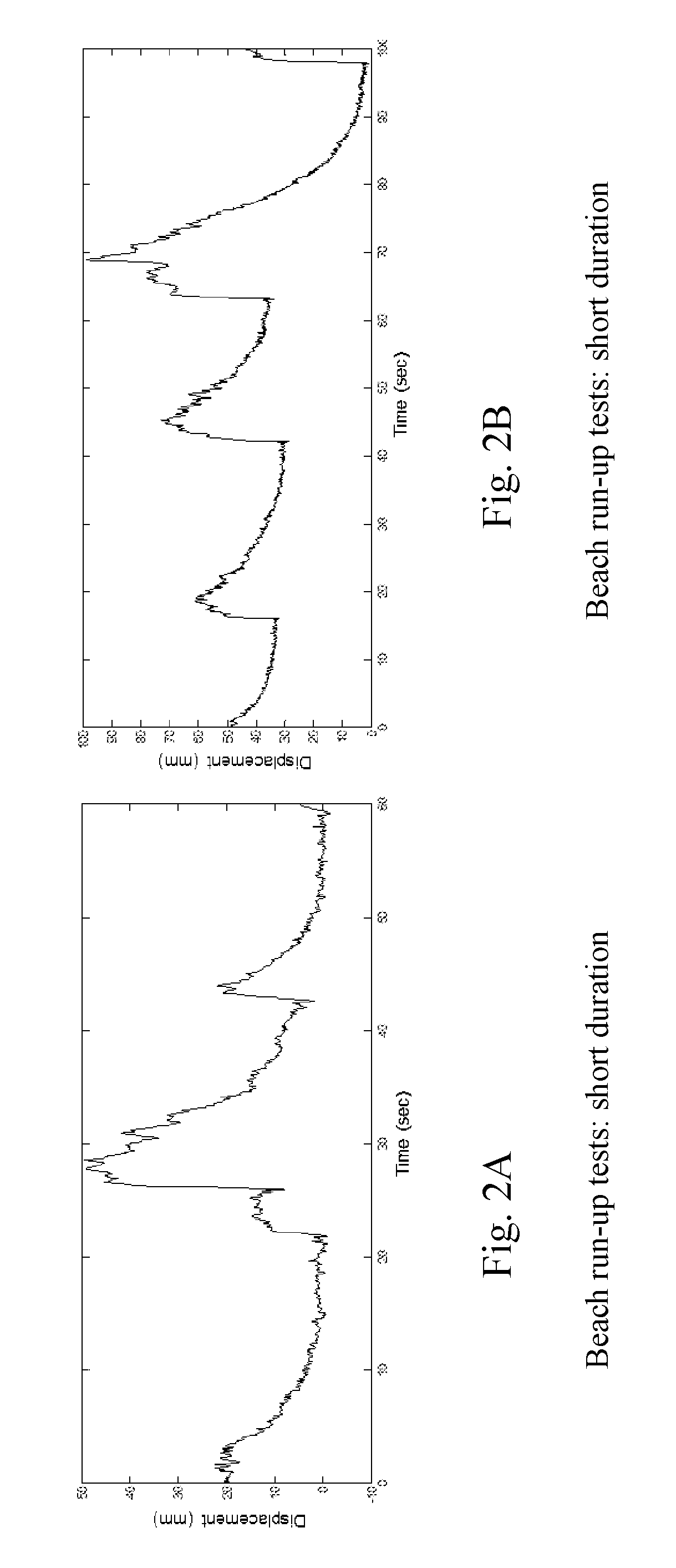
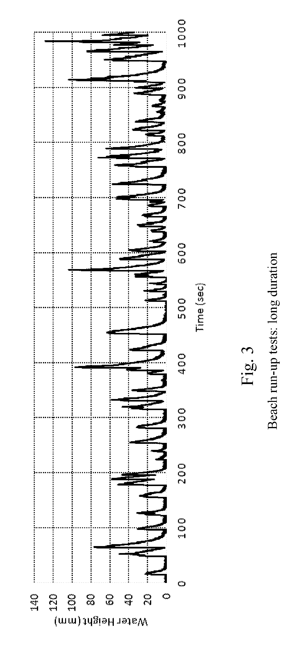
Devices, methods and systems for wave and water level measurement using a single DC (direct current)-coupled CW (continuous wave) Doppler radar for detecting water elevation changes in time when installed up to several meters from the water surface. The radar is wireless and can stream continuous data to a local PC (personal computer) or base station in range of its radio. The radar can sample up to 40 Hz and can run on batteries for continuous sampling. The radars can include multiple radar configurations of 1, 2 and 4 radar configurations. Applications for this radar can include the measurement of beach run-up, free surface elevation in tidal zones, and storm surge elevations near bridges and critical infrastructure during storm events.

Description

[0001]This application claims the benefit of priority to U.S. Provisional Patent Application Ser. No. 62 / 105,009 filed Jan. 19, 2015, which is incorporated by reference in its' entirety.FIELD OF THE INVENTION[0002]This invention relates to water monitoring equipment and, in particular, to methods, systems and devices for continuous wave (CW) interferometric Doppler radar wave and water level indicator using wireless radar sensor for displacement and distance measurement in time including water surface elevation and characteristic measurement integrated as a single device or a network of devices for applications such as storm surge tracking and tidal zone assessment.BACKGROUND AND PRIOR ART[0003]Traditional water level gauging instruments are generally in contact with the water itself (susceptible to biofouling) or include relatively expensive non-contact equipment that is relatively inaccurate when used.[0004]Some traditional water level gauging method consists of a massive station ...

Claims


Application Information

Patent Timeline
Patent Type & Authority Patents(United States)
IPC IPC(8): G01F23/284G01S13/58G01S13/87G01S7/00G01S13/36G01S13/70G01S13/88G01S7/35
CPCG01S7/003G01S13/36G01S13/70G01S13/88G01S13/583G01F23/284G01S13/87G01S2007/358G01S7/358
Inventor BRIDGE, JENNIFER ANNELI, CHANGZHIGU, CHANGZHANDAVIS, JUSTIN R.
Owner UNIV OF FLORIDA RES FOUNDATION INC
Why Eureka
Try Eureka