Exhaust gas purification system and ship having the same

a technology of exhaust gas purification system and exhaust gas, which is applied in the direction of machines/engines, mechanical equipment, separation processes, etc., can solve the problems of long bypass path piping distance, nox catalyst performance degradation, and nox catalyst clogging with soot or particulates, so as to reduce the manufacturing cost of the combined casing and facilitate the formation of two paths , the effect of simplifying the exhaust structur

Active Publication Date: 2019-10-15
YANMAR POWER TECHNOLOGY CO LTD
View PDF35 Cites 1 Cited by
  • Summary
  • Abstract
  • Description
  • Claims
  • Application Information

AI Technical Summary

Benefits of technology

[0006]If global environment is taken into consideration, it is necessary to remove NOx in exhaust gas as much as possible, and it is preferable to regulate the NOx uniformly in both the high seas and closed sea. However, under present circumstances, as higher exhaust gas regulation concerning the diesel engine is applied, it is scheduled to provide regulation marine area concerning NOx. Since the NOx catalyst is of the honeycomb structure as described above, there is fear that the NOx catalyst becomes clogged with soot or particulates. Performance of the NOx catalyst is deteriorated by a sulfur component in exhaust gas and a product caused by the sulfur. To extend the lifetime of the NOx catalyst as long as possible and to reduce running costs and to reliably comply with the regulation in the regulation marine area, it is considered that the NOx catalyst is not exposed to exhaust gas during sailing along marine area other than regulation marine area.
[0007]Hence, the present applicant previously proposed that a purification casing for accommodating NOx catalyst therein was provided in an exhaust gas path, and a bypass path through which exhaust gas bypassed branched off from the exhaust gas path upstream side of the purification casing without passing through the NOx catalyst (see Japanese Patent Application Laid-open No. 2010-71149 for example). In this case, exhaust gas is sent toward the purification casing during sailing in the regulation marine area, and exhaust gas is sent toward the bypass path during sailing in marine area other than the regulation marine area. Hence, it is possible to extend the lifetime of the NOx catalyst, and there are advantages that the running costs are cut down, and the purification performance can be maintained for a long time.

Problems solved by technology

Since the NOx catalyst is of the honeycomb structure as described above, there is fear that the NOx catalyst becomes clogged with soot or particulates.
Performance of the NOx catalyst is deteriorated by a sulfur component in exhaust gas and a product caused by the sulfur.
According to the conventional structure, however, since the bypass path bypassing the NOx catalyst is provided separately from the exhaust gas path and the purification casing, there is a problem that a long piping distance of the bypass path is required, and the producing costs are increased.
Further, since an installation space of the bypass path is required separately from the purification casing, if an engine room of a ship is narrow, it may be difficult to install the bypass path.

Method used


Image

  • Exhaust gas purification system and ship having the same
  • Exhaust gas purification system and ship having the same
  • Exhaust gas purification system and ship having the same

Examples


first embodiment

(4). Operation and Effect of First Embodiment

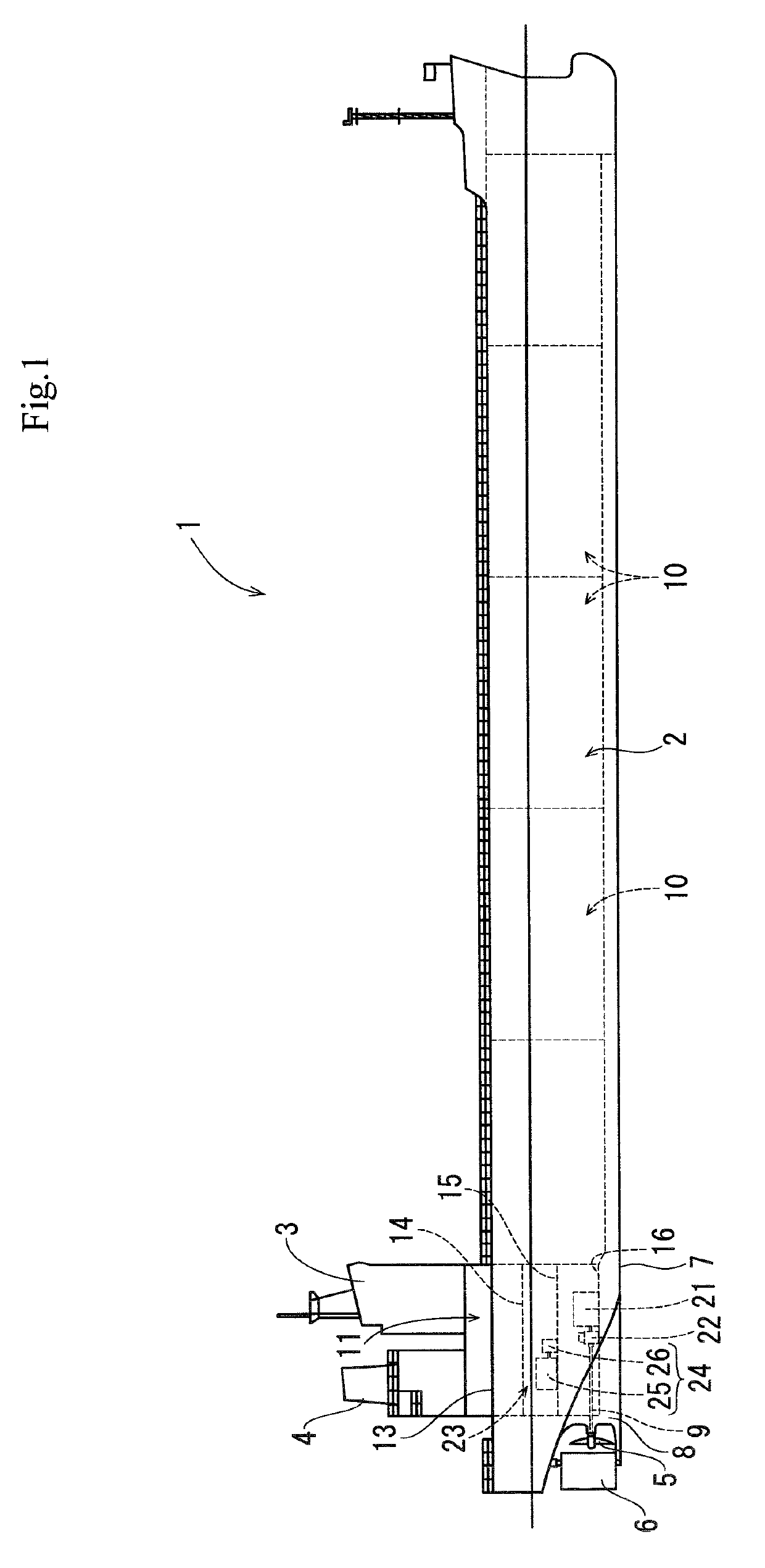
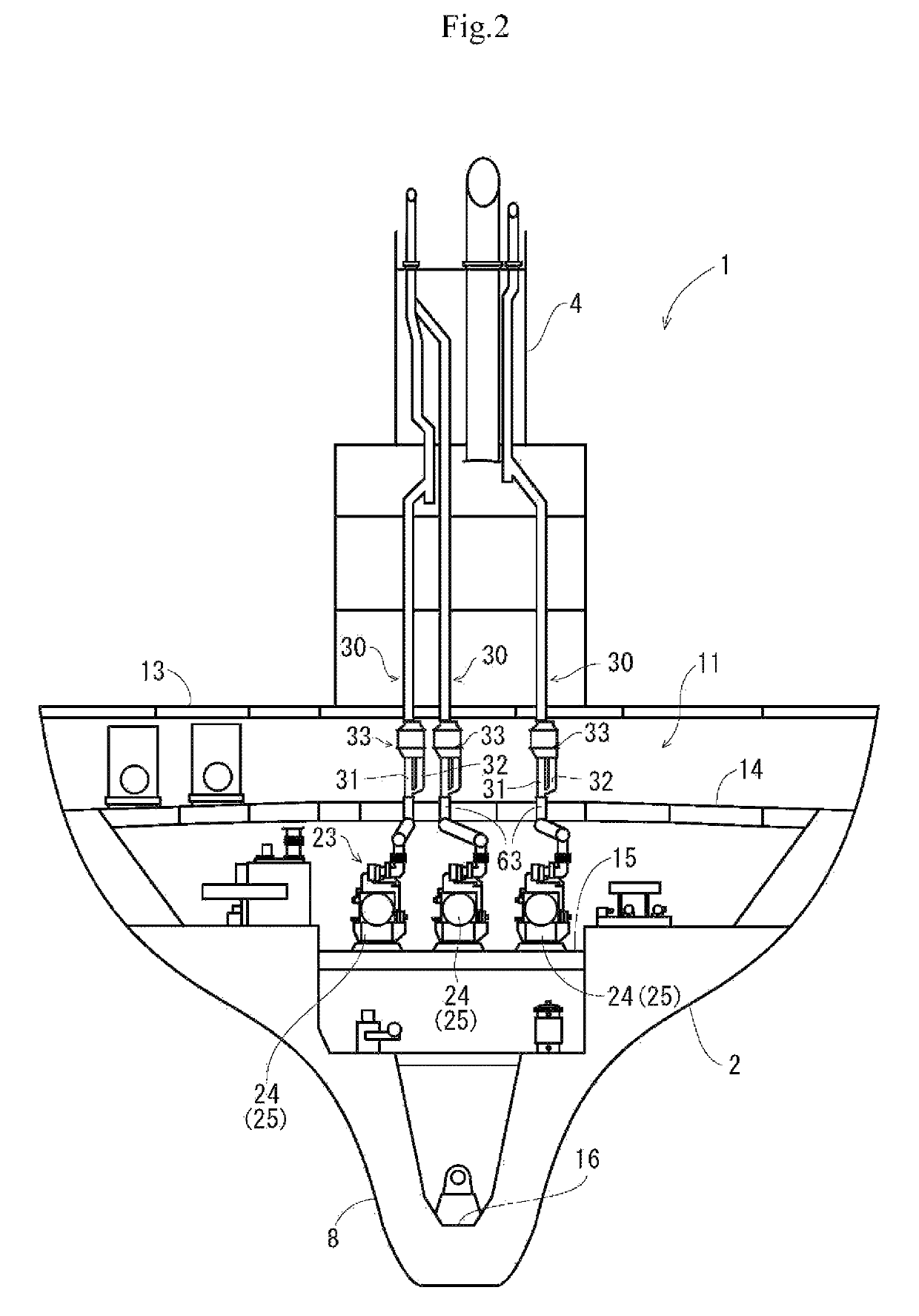
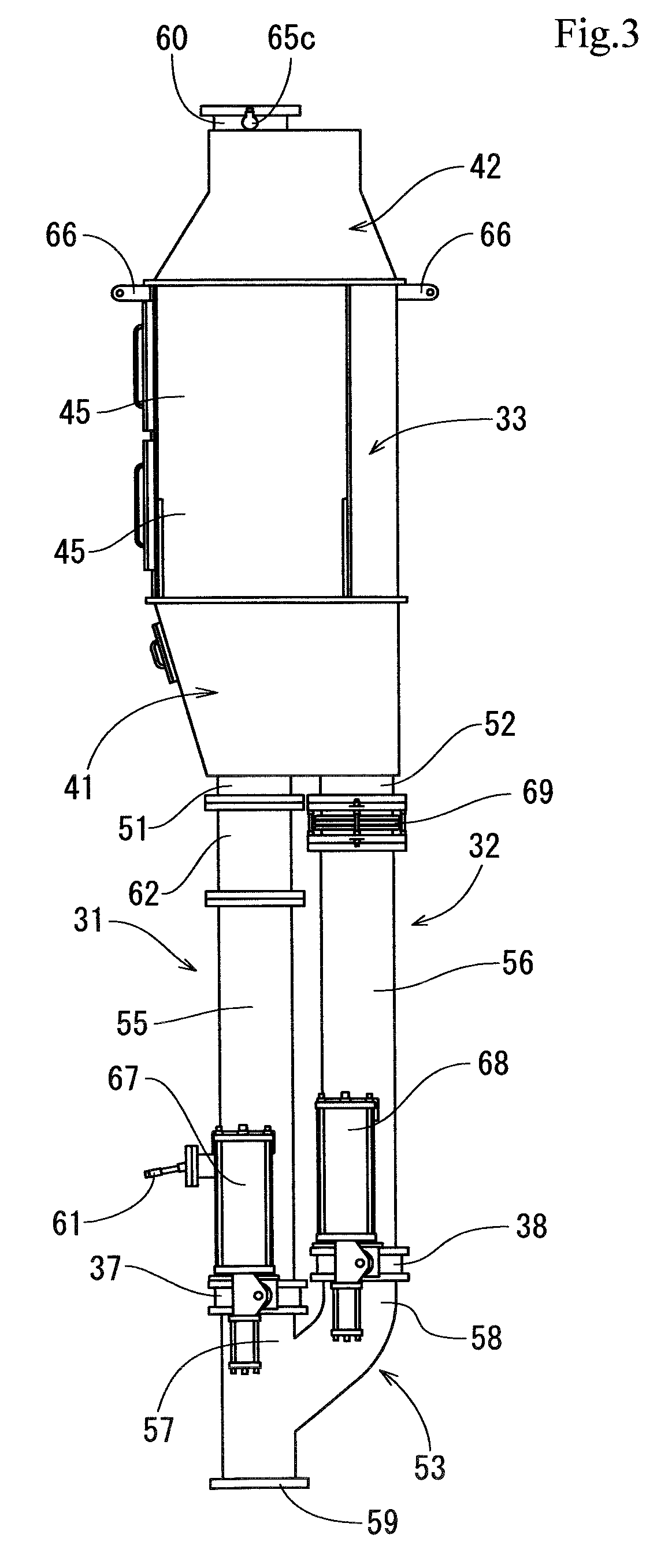
[0072]With the above-described configuration, the exhaust gas purification system includes, as exhaust gas paths 30 of an engine 25 to be mounted in a ship 1, a main path 31 which is in communication with outside and a bypass path 32 which branches off from a halfway portion of the main path 31, and includes a combined casing 33 with which both the main path 31 and the bypass path 32 are in communication, wherein a selective catalyst reduction device 34, 35 which accelerates reduction of NOx existing in exhaust gas of the engine 25 is accommodated in the combined casing 33 at a location close to the main path 31, a path-switching member 37, 38 which switches exhaust gas moving directions between the main path 31 and the bypass path 32 is placed in a branched portion 53 between the main path 31 and the bypass path 32, and a reducing agent injection body 61 of a reducing agent supply device which supplies reducing agent to exhaust gas is pl...

second embodiment

(6). Operation and Effect of Second Embodiment

[0079]As described also in the first embodiment, in the case of the conventional ship 1 having a plurality of auxiliary engines (e.g., power-generating engines) which are engines 25, since the ship 1 separately includes the main path 31 and the bypass path 32, twice number of exhaust gas paths as the engines 25 are required, the bypass path 32 must be assembled in a shipbuilding yard, and the number of operation steps is increased. According to the configuration of the second embodiment, on the other hand, the exhaust gas paths 30 are gathered and then, the main path 31 and the bypass path 32 as the assembly path 80 are gathered in the combined casing 33. Therefore, it is possible to extremely simplify the exhaust structure of the ship 1 having the plurality of engines 25. The assembling operation of the bypass paths 32 in the shipbuilding yard is unnecessary, the number of operation steps can be reduced and the costs can be cut down. Th...


PUM

PropertyMeasurementUnit
areaaaaaaaaaaa
conical shapeaaaaaaaaaa
cross-sectional areaaaaaaaaaaa

Abstract

An exhaust gas purification system includes, as an exhaust gas path of an engine to be mounted in a ship, a main path which is in communication with outside, a bypass path which branches off from a halfway portion of the main path, and a combined casing with which both the main path and the bypass path are in communication. A selective catalyst reduction device is accommodated in the combined casing at a location close to the main path. A path-switching member which switches exhaust gas moving direction is placed in a branched portion between the main path and the bypass path. A reducing agent injection body is placed in the main path between the path-switching member and the combined casing.

Description

TECHNICAL FIELD[0001]The present invention relates to an exhaust gas purification system which removes a harmful component in exhaust gas discharged from an engine mounted in a ship, and also relates to a ship having the exhaust gas purification system.BACKGROUND OF THE INVENTION[0002]In a conventional ship such as a tanker and a transport vessel, an amount of electricity consumed by various auxiliary equipment, a cargo device, illumination, an air conditioner and other devices is huge, and to supply electricity to these electric devices, the ship includes a diesel power generator in which a diesel engine and a power generator for generating electricity by a driving operation the diesel engine are combined (see Patent Document 1 for example). It is known that the diesel engine is one of internal combustion engines having the highest energy efficiency, and an amount of carbon dioxide included in exhaust gas per unit output is small. Further, since the diesel engine can use low qualit...

Claims


Application Information

Patent Timeline
Patent Type & Authority Patents(United States)
IPC IPC(8): F01N3/20B01D53/94F01N3/28F01N13/08
CPCF01N2240/20F01N2410/00F01N2590/02F01N2610/02F01N2610/1453B01D53/9418B01D53/9431B01D2251/2067B01D2259/124B01D2259/4566F01N13/087F01N3/2066Y02T10/12F01N3/2892
Inventor YOKOYAMA, TETSUYAINOUE, TSUYOSHITAKAHATA, YASUYUKIHAMAOKA, SHUNJI
Owner YANMAR POWER TECHNOLOGY CO LTD
Why Eureka
Try Eureka