Automatic gain control based on signal spectrum sensing

a signal spectrum sensing and gain control technology, applied in the field ofspectrum analyzers, can solve the problems of tedious handling of automatic gain controller problems, and achieve the effect of removing the ambiguity of frequency location

Active Publication Date: 2019-10-29
SIGNALCHIP INNOVATIONS
View PDF5 Cites 0 Cited by
  • Summary
  • Abstract
  • Description
  • Claims
  • Application Information

AI Technical Summary

Benefits of technology

[0009]In one embodiment, the system further (i) removes ambiguity of a frequency of one or more signal components, (ii) reconstructs a signal power profile of the input signal at one or more locations with knowledge of a filtering response of signal processing chains, and (iii) selects optimum mode using reconstructed signal power profile and knowledge of a circuit non linearity. In another embodiment, the optimum mode is determined based on determination of the locations of the interference signal and the signal power profile and the knowledge of the circuit non linearity. In yet another embodiment, the ambiguity in an actual frequency location of the signal is removed by relating the signal whose frequency measured after sampling appears in an invalid region and further whose real frequency value is mapped to most likely valid transmit frequency by considering other aliasing frequencies. In yet another embodiment, the system further includes a decimation filter chain that (i) estimates a energy of the signal at output of each of one or more tap off points, (ii) estimates a energy of the signal at input of each of the one or more tap off points, (iii) compares the energy estimated at the output of each of the one or more tap off points with the energy estimated at the input at each of the one or more tap off points to estimate the energy distribution of the input signal. In yet another embodiment, the system further determines (i) an exact location of occurrence of loss of energy, and (ii) location of the interference frequency by comparing the measured energy at input and output of each of the one or more filtering stages.

Problems solved by technology

When the gain attenuation and filtering stages are interleaved (typical in integrated analog front ends) the automatic gain controller problem is a more tedious to deal with since in most environments, the intermediate points in the receive path are inaccessible.

Method used


Image

  • Automatic gain control based on signal spectrum sensing
  • Automatic gain control based on signal spectrum sensing
  • Automatic gain control based on signal spectrum sensing

Examples


Embodiment Construction

[0020]The embodiments herein and the various features and advantageous details thereof are explained more fully with reference to the non-limiting embodiments that are illustrated in the accompanying drawings and detailed in the following description. Descriptions of well-known components and processing techniques are omitted so as to not unnecessarily obscure the embodiments herein. The examples used herein are intended merely to facilitate an understanding of ways in which the embodiments herein may be practiced and to further enable those of skill in the art to practice the embodiments herein. Accordingly, the examples should not be construed as limiting the scope of the embodiments herein.

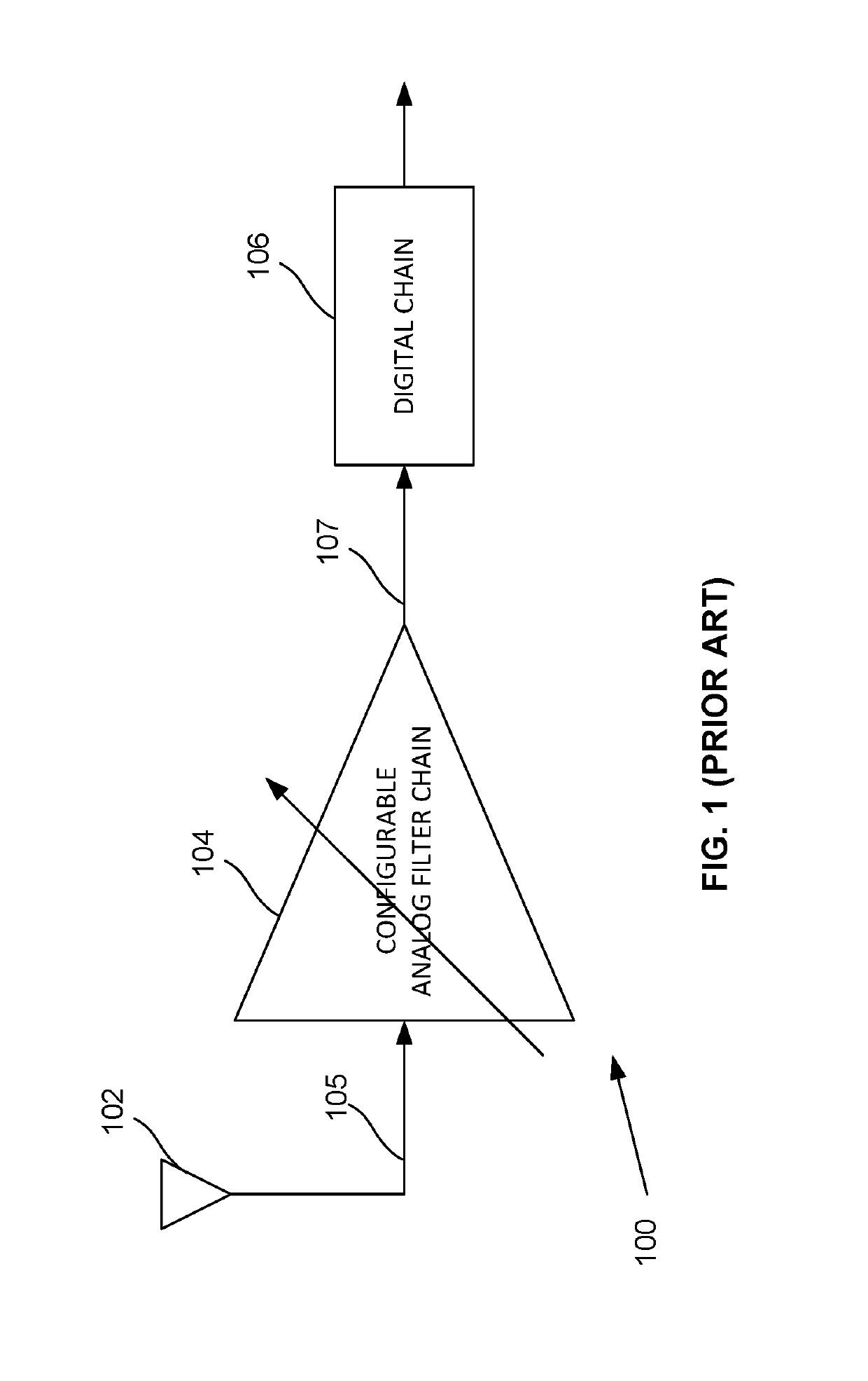
[0021]A typical receiver architecture is shown in FIG. 1. The architecture 100 as depicted in FIG. 1 represents a typical receiver implementation, in accordance with an exemplary scenario. An analog filter chain 104 receives an RF signal 105 from a transmission station through an antenna 102. A...


PUM


Abstract

Disclosed herein is a method for automatic gain control based on signal spectrum sensing. Spectral sensing techniques may be employed to detect the presence or absence of interference and also determine a frequency location of the interference and power level estimates of a desired signal. The method includes running an algorithm to measure the energy periodically to track the changes as blockers that were not prominent while experiencing deep fade and those that will affect performance when it is out of the deep fade. The method enables predicting a level of degradation for various front-end settings and enables selection of an optimum setting. In an embodiment, the spectral sensing may be performed either in analog domain using narrowband tunable filters. In an embodiment, the spectral sensing may be performed digitally using Fast fourier transform (FFT), Goertzel algorithm, or power detection techniques.

Description

CROSS-REFERENCE TO RELATED APPLICATIONS[0001]This application claims priority to Indian patent application no. 4735 / CHE / 2015 filed on Sep. 7, 2015, the complete disclosure of which, in its entirely, is herein incorporated by reference.BACKGROUNDTechnical Field[0002]The embodiments herein generally relate to spectrum analyzer, and, more particularly, to a method and system for automatic gain control based on signal spectrum sensing using a Fast Fourier Transform (FFT) analysis, a Goertzel analysis, and a power level estimate.Description of the Related Art[0003]Many current and future generations of communication devices, such as mobile handsets, ultra mobile devices (UMD) and laptop PCs (Personal Computer) have wireless transmitters and / or receivers of different communication technologies integrated into a single or same host device. These communication technologies may involve, for example, cellular radio technologies, such as GSM (Global System for Mobile communication), PCS (Perso...

Claims


Application Information

Patent Timeline
Patent Type & Authority Patents(United States)
IPC IPC(8): H04W52/52H04B17/391H04B17/373H04L27/26
CPCH04W52/52H04L27/2647H04B17/373H04B17/3911
Inventor GANESAN, ARAVINDKHASNIS, HIMAMSHU GOPALAKRISHNA
Owner SIGNALCHIP INNOVATIONS
Why Eureka
Try Eureka