Minimally invasive mitral valve replacement with brim

a technology of mitral valve and brim, which is applied in the field of minimally invasive prosthetic heart valve, can solve the problems of increasing the risk of embolism, affecting the health of patients, and too much disease in the valve to be repaired and replaced,

Active Publication Date: 2019-11-05
VENUS MEDTECH (HANGZHOU) INC
View PDF64 Cites 2 Cited by
  • Summary
  • Abstract
  • Description
  • Claims
  • Application Information

AI Technical Summary

Benefits of technology

[0051]Another advantage of the present invention is, when mounting a valve into or onto a tube it is better to have three, or possibly more, leaflets than only two. When making two leaflets only, the leaflets' free edge length is equal to the diameter of the valve which does not allow the leaflets to open up much and to provide a large opening orifice. Rather, the resulting orifice is just a slit. However, when providing three leaflets, the valve leaflets free edge can open up widely, creating a large and possibly circular orifice upon opening. Thus providing three leaflets has physical, mechanical and fluid dynamic reasons equal to the situation in the aortic valve. In contrast, the native mitral valve can work with only two leaflets only since the two leaflets work like two sails but not like cusps in the aortic valve.
is, when mounting a valve into or onto a tube it is better to have three, or possibly more, leaflets than only two. When making two leaflets only, the leaflets' free edge length is equal to the diameter of the valve which does not allow the leaflets to open up much and to provide a large opening orifice. Rather, the resulting orifice is just a slit. However, when providing three leaflets, the valve leaflets free edge can open up widely, creating a large and possibly circular orifice upon opening. Thus providing three leaflets has physical, mechanical and fluid dynamic reasons equal to the situation in the aortic valve. In contrast, the native mitral valve can work with only two leaflets only since the two leaflets work like two sails but not like cusps in the aortic valve.

Problems solved by technology

Stenosis is one problem that heart valves may develop in which a valve does not open properly, another is insufficiency, or regurgitation, where a valve fails to close properly.
Sometimes such a problem can be treated by surgical repair of a valve; however, often a valve is too diseased to repair and must be replaced.
Mechanical or artificial valves are typically constructed from non-biological materials, such as plastics, metals and other artificial materials which, while durable, are prone to blood clotting which increases the risk of an embolism.
Anticoagulants which may be taken to prevent blood clotting can possibly complicate a patient's health due to increased risk of hemorrhage.
The major disadvantage of tissue valves is that they lack the long-term durability of mechanical valves.
In instances where a patient is deemed operable only at too high a surgical risk, one alternative in valve stenosis has been to dilate the native valve with a balloon catheter to enlarge the valve orifice; however, such practice has experienced a high restenosis rate.
However, there is only limited space available within the vasculature; thus, the surgical field is often only as large as the diameter of a blood vessel.
Consequently, the introduction of tools and prosthetic devices becomes greatly complicated, and the device to be implanted must be dimensioned and configured to permit it to be introduced into the vasculature, maneuvered therethrough, and then positioned at a desired location.
Delivery of bulky tools and prosthetic devices retrograde through an atheromatous aortic vessel has increased risk of injuring of the atheromatous aortic wall with subsequent potential embolism and even aortic wall rupture.
In spite of all improvements achieved in the field of aortic valve replacement, there is still a lack in promising mitral valve replacement techniques and suitable mitral valve devices.

Method used


Image

  • Minimally invasive mitral valve replacement with brim
  • Minimally invasive mitral valve replacement with brim
  • Minimally invasive mitral valve replacement with brim

Examples


Embodiment Construction

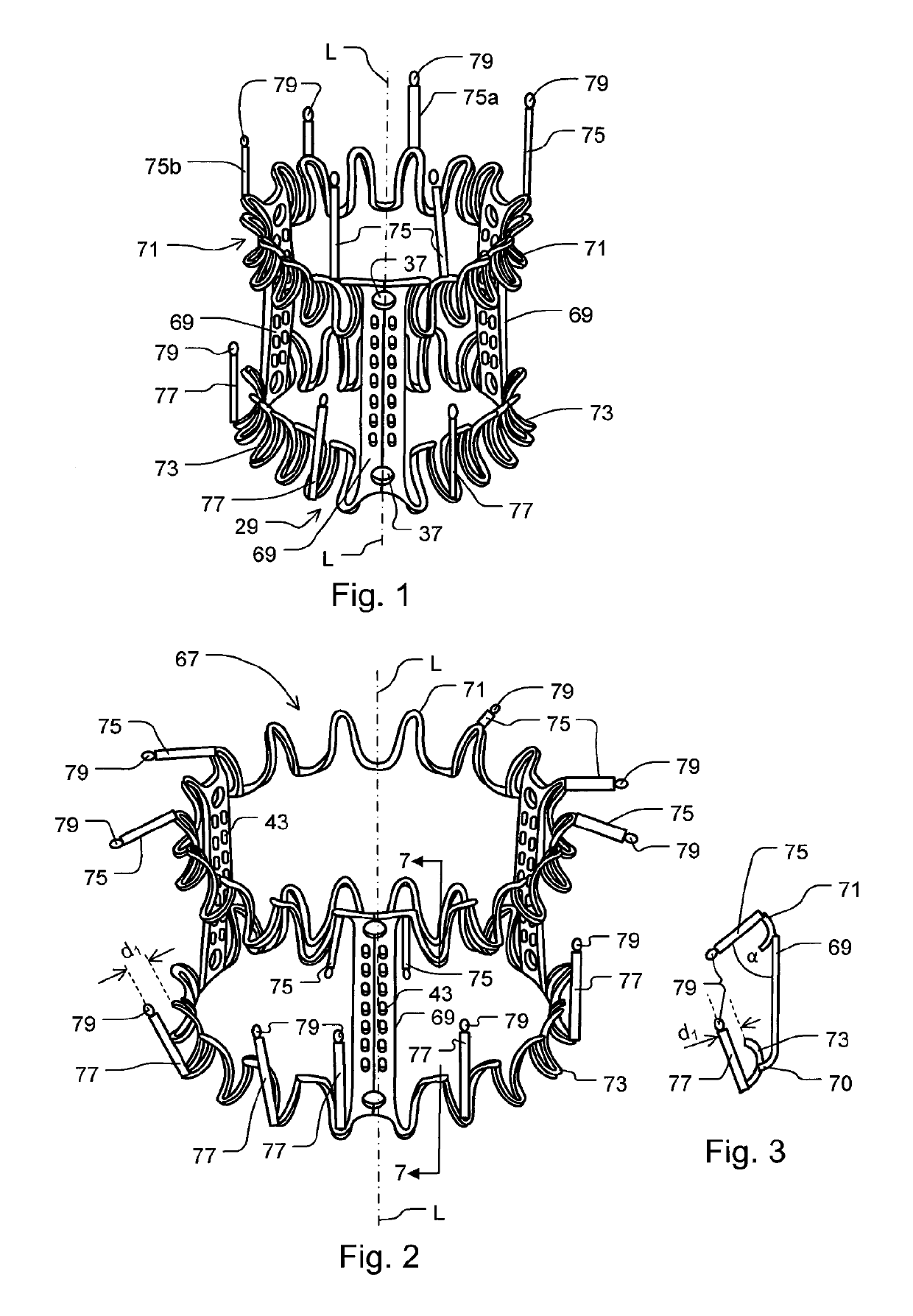
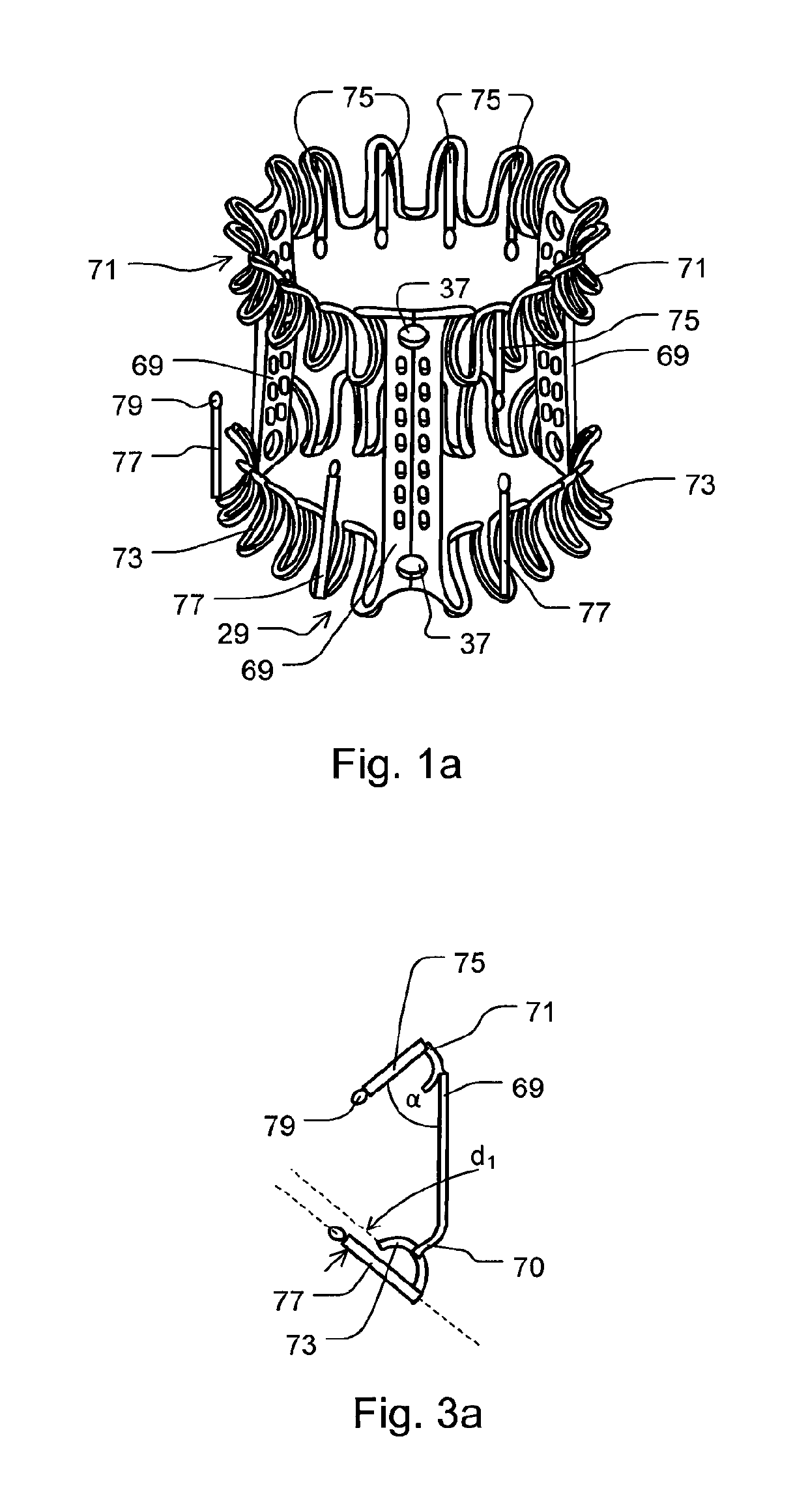
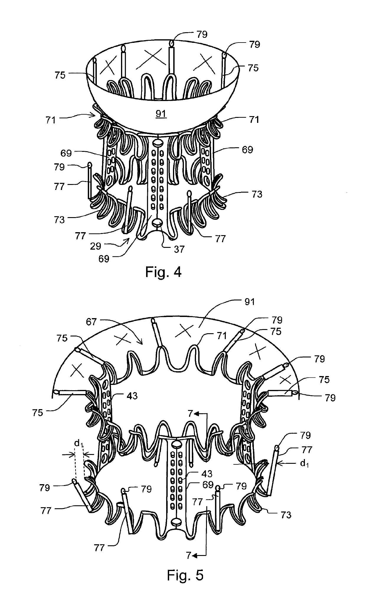
[0062]A first preferred embodiment of a tubular stent 29 incorporating various features of the invention is shown in FIG. 1 through FIG. 6 whereas FIG. 1a shows another preferred embodiment. The tubular stent 29 has a tubular deployment form with a longitudinal axis L and is optionally surrounded with a covering layer of biocompatible thin sheet material (not shown). It is designed to be deployed in a collapsed condition using a delivery implement where it is slidably disposed within or on a catheter that is caused to enter the body through a vein or through a cannula implanted intercostally in the chest, through which it is directed through a atrial wall or the left ventricular wall of the heart and, for example, and then through the orifice of the mitral valve.

[0063]The tubular stent 29 can be made of wire-like material, which may be of circular, square, rectangular, oval or other cross section, of a shape-alloy material which has sufficient elasticity such that it can be manually...


PUM


Abstract

A collapsible-expandable tubular stent (29) constructed of shape-memory material which is implantable into a human heart, which comprises proximal and distal rings (71, 73) and at least two spaced apart posts (69) that extend axially between said rings (71, 73), said distal ring (73) comprising a plurality of distal arms (77) which are connected to the distal ring (73) at only one end and which have a free opposite end; said proximal ring (71) comprising a plurality of, which are connected at only one end to the proximal ring (71) and which have a free opposite end, which proximal arms (75) are constructed to swing radially outward at their free ends.

Description

FIELD OF THE INVENTION[0001]The present invention relates to a prosthetic valve for implantation in the heart in a minimally invasive or percutaneous manner, and more particularly to a prosthetic heart valve suitable for replacement of a mammal heart valve, most particularly an atrio-ventricular valve, a mitral valve and a tricuspid valve.BACKGROUND OF THE INVENTION[0002]Four valves in the heart serve to direct the flow of blood through the two sides of the heart in a forward direction. The mitral valve, located between the left atrium and the left ventricle, and the aortic valve, located between the left ventricle and the aorta, constitute the systemic portion of the heart. These two valves direct oxygenated blood coming from the lungs through the left side of the heart into the aorta for distribution throughout the body. The right side of the heart includes the tricuspid valve, located between the right atrium and the right ventricle, and the pulmonary valve, located between the r...

Claims


Application Information

Patent Timeline
Patent Type & Authority Patents(United States)
IPC IPC(8): A61F2/24
CPCA61F2/2418A61F2250/006A61F2210/0014A61F2/2439A61F2220/0008A61F2250/0006
Inventor LIM, HOU-SENGOTZ, WOLFGANG
Owner VENUS MEDTECH (HANGZHOU) INC
Why Eureka
Try Eureka