Co2 Z-type ferrite composite material for use in ultra-high frequency antennas
a composite material and ultra-high frequency technology, applied in the direction of iron compounds, cobalt compounds, magnetic bodies, etc., can solve the problems of not meeting the need for the design of a practical antenna, difficult to develop ferrite materials for such high frequency applications, and known ferrite materials that exhibit relatively high magnetic loss at high frequencies
- Summary
- Abstract
- Description
- Claims
- Application Information
AI Technical Summary
Benefits of technology
Problems solved by technology
Method used
Image
Examples
example 1
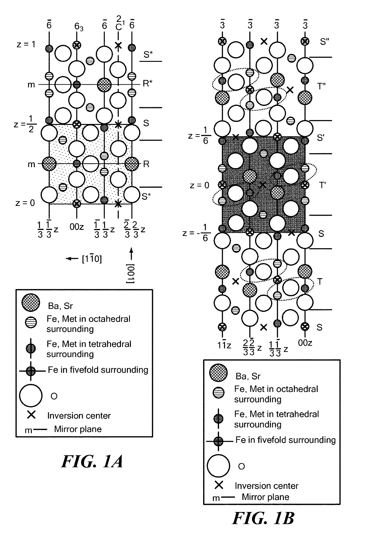
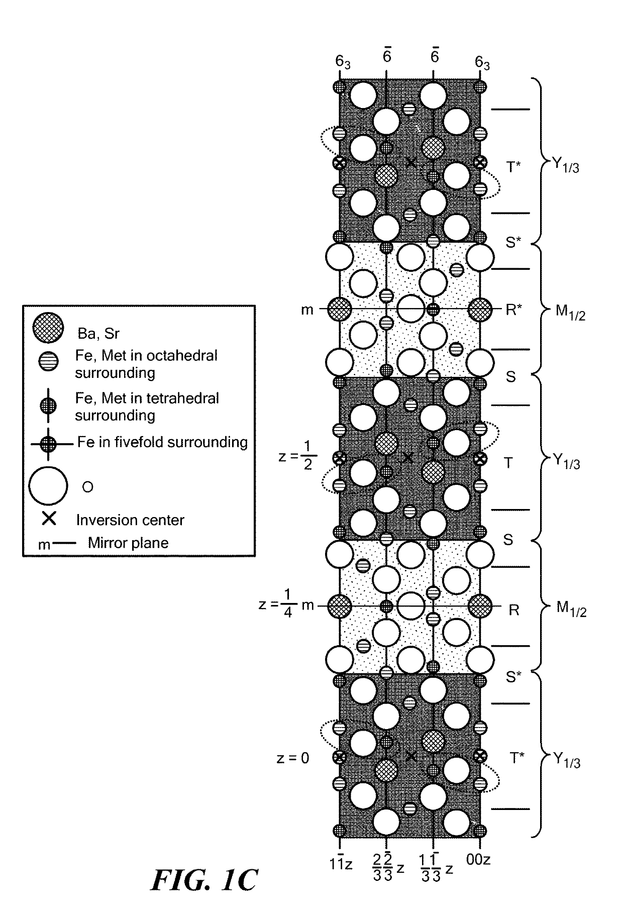
[0034]Polycrystalline Co2Z ferrites, having the composition Ba3Co2+xIrxFe24-2xO41, where x=0, 0.05, 0.10, 0.15 and 0.20, were prepared by a ceramic process. Starting materials of BaCO3, IrO2, Co3O4, and Fe2O3 were calcined in air for 6 hours at 1000° C. to form the ferrite phases, and then crushed and ball milled. A mixture was prepared comprising 90 vol. % ferrite fine powders and 10 vol. % polyvinyl alcohol (PVA) binder, and was pressed into a toroid with an outer diameter of 7 mm, inner diameter of 3 mm, and width of about 2 mm. This sample size is adequate for microwave measurements. The ferrite samples were sintered at 1250-1280° C. for 4 hours in an oxygen atmosphere.
[0035]X-ray diffraction (XRD) characterization of the crystallographic structure of the resulting ferrite compositions revealed a Z-type phase accompanied by increasing amounts of Y-type phase as the iridium amount was increased. The Y-type phase appeared as a secondary phase with the doping of iridium and helped ...
example 2
[0041]The effect of the additive Bi2O3 upon the real and complex permittivity and permeability of the composite ferrites was also examined. Samples labeled A, B and C with various amounts of Bi2O3 (ranging from 0.2 to 5.0 wt. %) and iridium amounts (x=0.12-0.15) were prepared for microwave measurements. The amounts of Bi2O3 and Ir are indicated in Table 2.
[0042]
TABLE 2ABCBi2O32-5 wt. %0.5-3 wt. %0.1-1.0 wt. %Irx = 0.12-0.20x = 0.08-0.15x = 0.12-0.20
FIG. 5 shows the relative real permittivity ∈′ and real permeability μ′ spectrum and dielectric and magnetic loss of the three samples in the frequency range from 0.3 GHz to 1 GHz. The values of real permittivity ∈′ are very close to those of the real permeability μ′ for all three samples. Sample C shows the best performance in impedance match to free space with almost equal values of real permittivity ∈′ and real permeability μ′. As for the dielectric and magnetic loss, all three samples have relatively lower loss tan δ∈ and loss tan δμ ...
PUM
| Property | Measurement | Unit |
|---|---|---|
| frequency | aaaaa | aaaaa |
| frequency | aaaaa | aaaaa |
| grain size | aaaaa | aaaaa |
Abstract
Description
Claims
Application Information
 - R&D
- Intellectual Property
- Life Sciences
- Materials
- Tech Scout
- Unparalleled Data Quality
- Higher Quality Content
- 60% Fewer Hallucinations
Browse by: Latest US Patents, China's latest patents, Technical Efficacy Thesaurus, Application Domain, Technology Topic, Popular Technical Reports.
© 2025 PatSnap. All rights reserved.Legal|Privacy policy|Modern Slavery Act Transparency Statement|Sitemap|About US| Contact US: help@patsnap.com


