RF generator

a generator and generator technology, applied in the field of rf generators, can solve problems such as excessive output, and achieve the effect of reducing the variation of output power

Active Publication Date: 2019-11-26
KOKUSA ELECTRIC CO LTD
View PDF10 Cites 1 Cited by
  • Summary
  • Abstract
  • Description
  • Claims
  • Application Information

AI Technical Summary

Benefits of technology

[0005]In accordance with the RF generator, the variation in output power can be reduced.

Problems solved by technology

In an RF generator, when the load impedance varies, the output level varies due to the variation in the load impedance, which may result in an excessive output.

Method used


Image

  • RF generator
  • RF generator
  • RF generator

Examples


embodiment

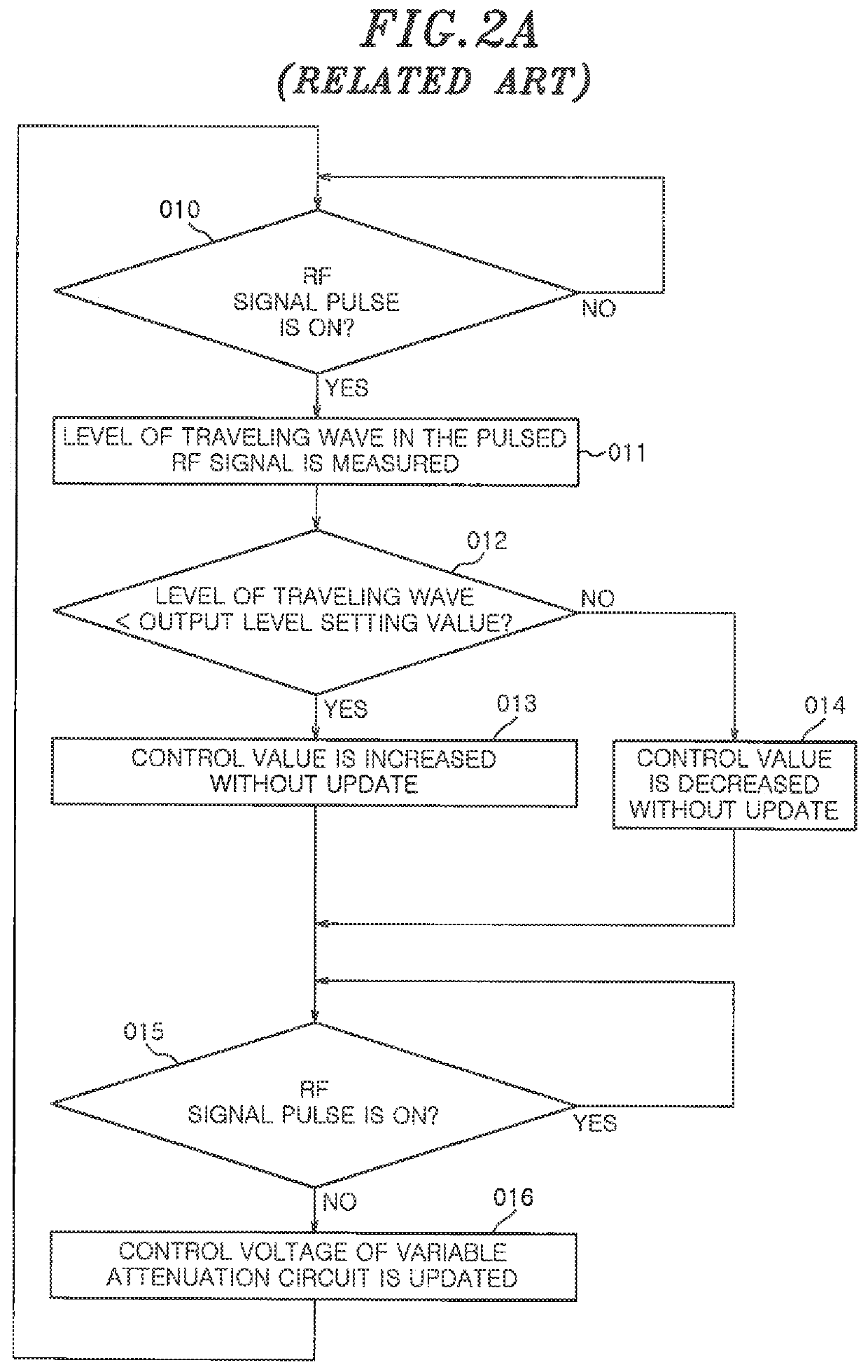
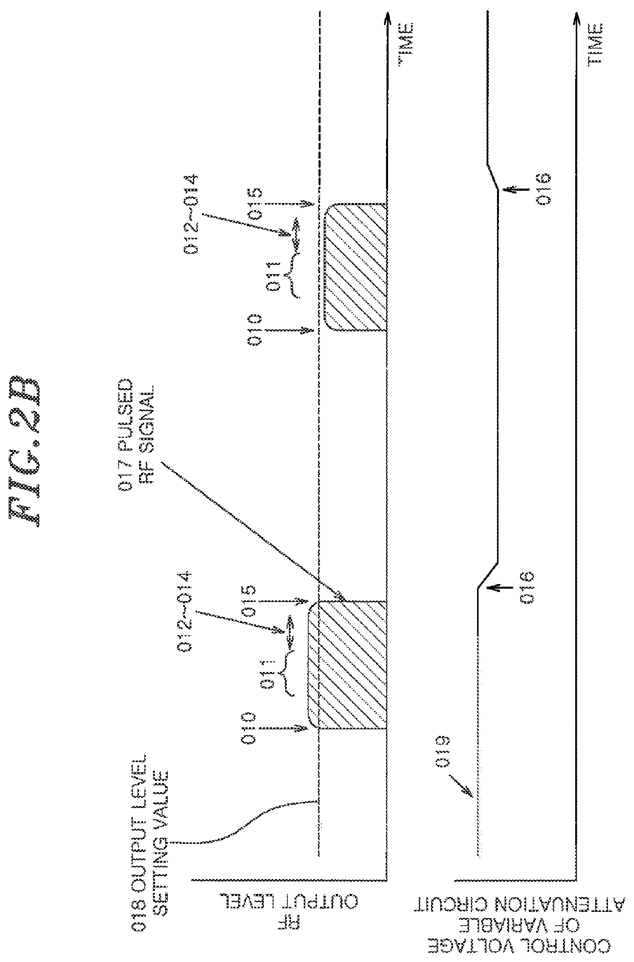
[0032]An RF power supply according to an embodiment employs a method of switching a level control in a pulsed RF signal in two stages. (a) In the first stage, the level control is performed for a section where the load impedance varies in the vicinity of the leading end of the pulse. (b) In the second stage, the level control is performed for a section where the output is stabilized due to the stabilization of the load impedance. The two-stage level control is performed by switching the control voltage of the variable attenuation circuit.

[0033]In accordance with the embodiment, it is possible to suppress the excessive output caused by the change in the load impedance (laser or the like), stabilize the output, and suppress temporal deterioration to prevent breakage of the RF power supply.

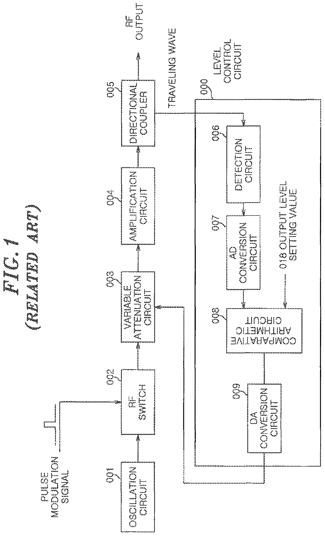
[0034]The present embodiment will be described with reference to FIG. 4. FIG. 4 schematically shows a configuration of a pulse-modulated RF generator according to the embodiment. The pulse-modulated ...


PUM


Abstract

An RF generator includes: a modulation circuit outputting a pulsed RF signal; a variable attenuation circuit adjusting the level of the pulsed RF signal; an output power detecting unit detecting an output power value of the power output from the device; a first comparative arithmetic circuit outputting a first level control signal for controlling the level of the adjusted pulsed RF signal on the basis of a first detected voltage value and a set voltage value set in advance; a second comparative arithmetic circuit outputting a second level control signal for controlling the level of the adjusted pulsed RF signal on the basis of a second detected voltage value and the set voltage value; and a switching circuit switching between the value of the first level control signal and the value of the second level control signal depending on a switching timing setting value.

Description

FIELD OF THE INVENTION[0001]The present disclosure relates to an RF generator and is applicable to, e.g., a pulse-modulated RF generator.BACKGROUND OF THE INVENTION[0002]An RF generator is used as industrial equipment for supplying RF energy to a load device for generating plasma, laser or the like and performs surface treatment or processing by using plasma, laser or the like (e.g., Japanese Patent Application Publication No. 2014-175218.)SUMMARY OF THE INVENTION[0003]In an RF generator, when the load impedance varies, the output level varies due to the variation in the load impedance, which may result in an excessive output. In view of the above, the present disclosure provides an RF generator that reduces the variation in output power.[0004]In accordance with an aspect, there is provided an RF generator comprising: an oscillation circuit configured to output an RF signal having a predetermined frequency; a modulation circuit configured to convert the RF signal outputted from the ...

Claims


Application Information

Patent Timeline
Patent Type & Authority Patents(United States)
IPC IPC(8): H05H1/46H03K5/02H03K5/156H03C1/00H03K3/80
CPCH03K5/02H03K5/156H03K3/80H05H1/46H01J37/32082H01J37/32146H01J37/32174H01J37/32137
Inventor OSHIDA, YOSHIYUKINASU, KENJIFUJIMOTO, NAOYA
Owner KOKUSA ELECTRIC CO LTD
Why Eureka
Try Eureka