Decoupler as one-way clutch

a one-way clutch and decoupler technology, applied in the direction of slip couplings, couplings, hoisting equipments, etc., can solve the problems of high noise and vibration, deterioration of accessory components, and generation of vibration and noise, so as to reduce vibration and noise generated between the pulley and the alternator, reduce the impact transfer from the pulley to the belt, and improve the durability of the belt

Active Publication Date: 2019-12-10
HYUNDAI MOTOR CO LTD +1
View PDF4 Cites 0 Cited by
  • Summary
  • Abstract
  • Description
  • Claims
  • Application Information

AI Technical Summary

Benefits of technology

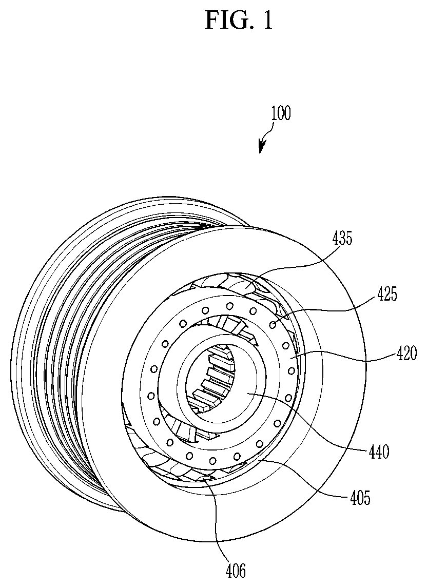
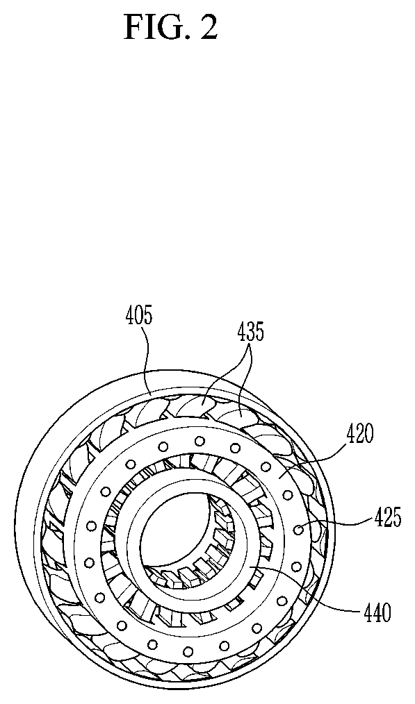
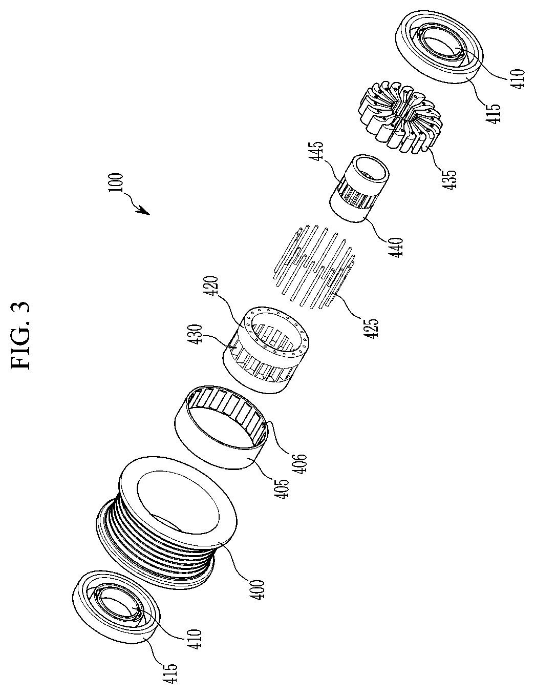
[0007]The present provides a decoupler having advantages of operating as a one-way clutch between a pulley and a hub, decreasing noise and a vibration generated in a belt internal combustion engine, improving durability of a belt wound around the pulley, and decreasing noise generated due to slip between the belt and the pulley.
[0012]According to the present invention for accomplishing these objects, the sprags may operate as a one-way clutch based on the sprag hub, and the lower end portions of the sprags may operate as a spring that absorbs a speed difference in a rotating direction between the sprag hub and the alternator hub. In addition, a vibration and noise generated between the pulley and the alternator may be decreased, and impact transferred from the pulley to the belt may be decreased to improve durability of the belt, and slip noise generated in the belt may be removed. Further, an overrunning state and a synchronous rotation state may be implemented, and a state in which rotation impact between the pulley and the alternator hub is absorbed may be implemented more easily.

Problems solved by technology

An internal combustion engine is operated by pulse type driving force, repeats acceleration and deceleration, and generates a vibration and noise.
Accordingly, due to a rapid variation of a speed and a vibration, durability of the belt driving accessory components may be deteriorated, and a high level of noise and vibration may be generated.
Additionally, rapid acceleration and deceleration of the engine, such as shifting, engine starting, and starting-off may cause slip between the belt and the pulley, as well as a high load on the belt.

Method used


Image

  • Decoupler as one-way clutch
  • Decoupler as one-way clutch
  • Decoupler as one-way clutch

Examples


Embodiment Construction

[0034]It is understood that the term “vehicle” or “vehicular” or other similar term as used herein is inclusive of motor vehicles in general such as passenger automobiles including sports utility vehicles (SUV), buses, trucks, various commercial vehicles, watercraft including a variety of boats and ships, aircraft, and the like, and includes hybrid vehicles, electric vehicles, combustion, plug-in hybrid electric vehicles, hydrogen-powered vehicles and other alternative fuel vehicles (e.g. fuels derived from resources other than petroleum).

[0035]The terminology used herein is for the purpose of describing particular embodiments only and is not intended to be limiting of the invention. As used herein, the singular forms “a”, “an” and “the” are intended to include the plural forms as well, unless the context clearly indicates otherwise. It will be further understood that the terms “comprises” and / or “comprising,” when used in this specification, specify the presence of stated features,...


PUM


Abstract

A decoupler is provided that includes a pulley around which a belt is wound. A sprag limiter is fixed to an interior circumference of the pulley and has protrusions formed at predetermined intervals in a circumferential direction on an interior circumference thereof. A sprag hub is disposed in the sprag limiter and has first apertures formed at predetermined intervals from an interior circumference to an exterior circumference thereof. A shaft hub is disposed in the sprag hub and has second apertures that are formed to correspond to the first apertures from an interior circumference to an exterior circumference thereof. Sprags having lower end portions are each inserted into the second apertures, central portions are each inserted into the first apertures, and upper end portions are in contact with the interior circumference of the sprag limiter, and allow the shaft hub to rotate in one direction based on the pulley movement.

Description

CROSS-REFERENCE TO RELATED APPLICATION[0001]This application claims priority to and the benefit of Korean Patent Application No. 2017-0086931 filed on Jul. 10, 2017, the entire contents of which are incorporated herein by reference.BACKGROUND(a) Field of the Invention[0002]The present invention relates to a decoupler, and more particularly, to a decoupler capable of decreasing a rotation vibration and noise, improving durability of a belt, and decreasing slip and noise generated by a pulley and the belt by generating a speed difference between the pulley and a hub.(b) Description of the Related Art[0003]It has been well-known to transfer a portion of an output shaft of an engine of a vehicle to belt driving accessory components using a serpentine belt in the engine. Generally, the respective components include pulleys fastened to the belt to thus be driven, and the belt is driven by an output pulley directly connected to a crankshaft of the engine. The pulley of the belt driving acc...

Claims


Application Information

Patent Timeline
Patent Type & Authority Patents(United States)
IPC IPC(8): F16D7/02F16H55/36F16D41/069F16D41/06
CPCF16D41/069F16D7/02F16H55/36F16D2041/0603F16H2055/366F16D41/06F16D7/048F02B67/06
Inventor CHOI, KUM LIMSHON, CHIWONLEE, KEUNSEOKKIM, UK HAN
Owner HYUNDAI MOTOR CO LTD
Why Eureka
Try Eureka