
Radiative cooling structures and systems

a cooling structure and radiation technology, applied in the field of radiation cooling structures and systems, can solve the problems of large power density mismatch between, and achieve the effects of convenient production and integration, improved efficiency, and improved efficiency

Active Publication Date: 2019-12-10
UNIV OF COLORADO THE REGENTS OF +1
View PDF36 Cites 5 Cited by
  • Summary
  • Abstract
  • Description
  • Claims
  • Application Information

AI Technical Summary

Benefits of technology

[0006]In some aspects, the present disclosure relates to polymer-based selective radiative cooling structures which include a wavelength-selective emissive layer of a polymer or a polymer matrix composite material. Exemplary wavelength-selective radiative cooling structures are in the form of a sheet, film or coating and can be viewed as providing a radiative cooling surface. In additional aspects, the disclosure relates to methods for removing heat from a body by selective radiation using polymer-based wavelength-selective radiative cooling structures. Additionally, the disclosure pertains to manufacturing methods for polymer-based radiative cooling structures. The polymer-based solutions for radiative cooling described herein can be cheaper, more effective and / or more easily produced and integrated at application size scales than inorganic multilayer optical coatings.
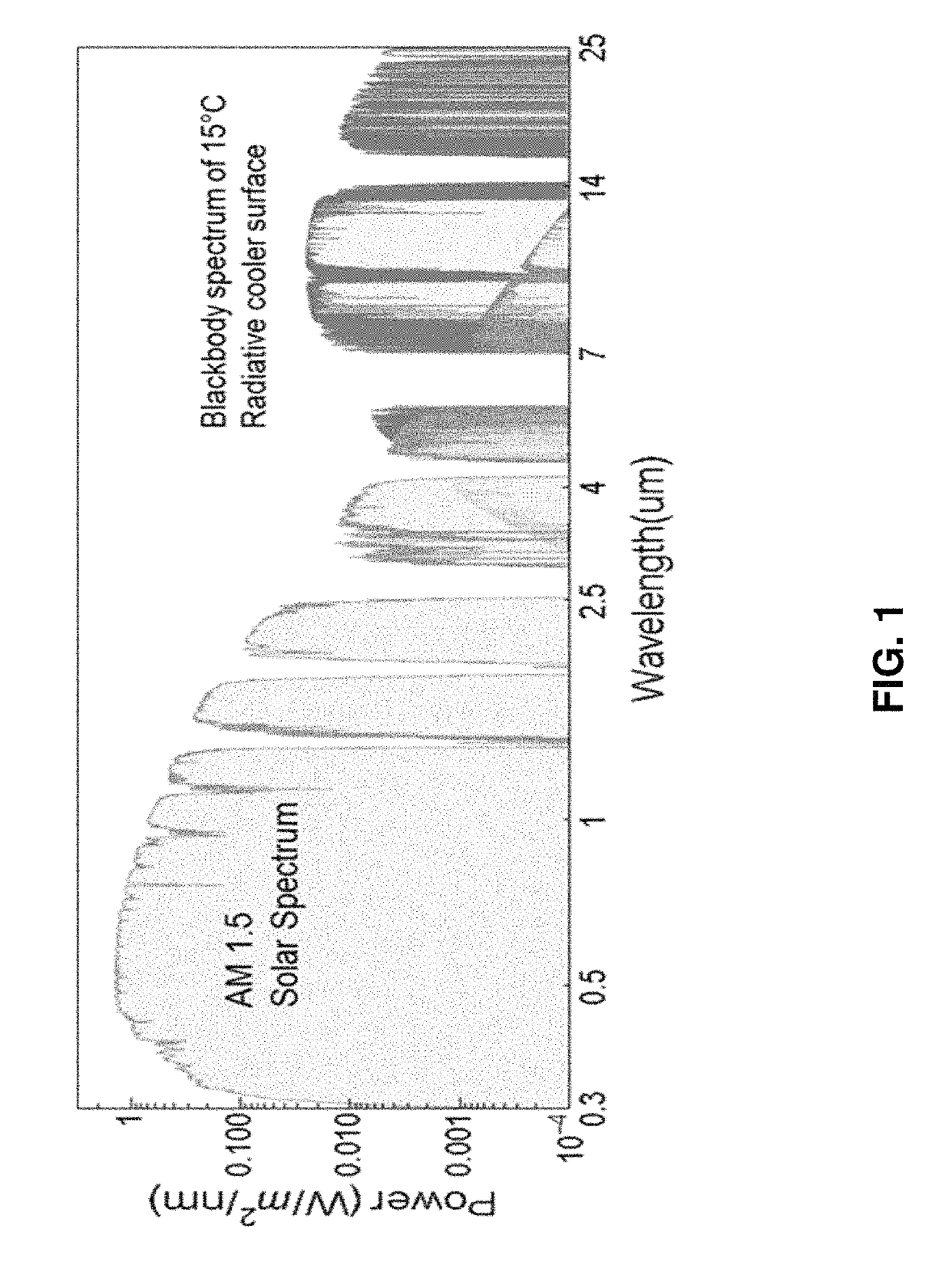
[0007]In some embodiments, the selective radiative cooling structures are selected to limit absorption of solar energy by the selective radiative cooling structure. FIG. 1 illustrates and compares the solar spectrum (AM1.5) and the thermal radiation spectrum for a blackbody at 15° C. through the atmospheric transmission windows. There is a large power density mismatch between the two spectra with relatively large heating power coming from the solar spectrum versus the potential self-cooling by thermal radiation through the atmospheric transmission window. In further embodiments, the selective radiative cooling structures maximize the infrared radiation in one or more atmospheric transmission windows.

Problems solved by technology

There is a large power density mismatch between the two spectra with relatively large heating power coming from the solar spectrum versus the potential self-cooling by thermal radiation through the atmospheric transmission window.

Method used


Image

  • Radiative cooling structures and systems
  • Radiative cooling structures and systems
  • Radiative cooling structures and systems

Examples


Embodiment Construction

[0081]In the drawings, like reference numbers refer to like elements.

[0082]The electromagnetic spectrum can be classified into several regions. Regions referred to herein are the infrared region (wavelength approximately 1 mm to 750 nm), visible region (wavelength approximately 750 nm to 400 nm) and the ultraviolet region (wavelength approximately 400 nm to 40 nm). The infrared region has also been classified into sub-regions using various classification schemes; in the ISO classification scheme the mid-infrared is approximately 3 μm to 50 μm. As used herein the radiant flux is the radiant energy per unit time (e.g. W), the irradiance is the radiant flux received by a surface per unit area (e.g. Wm−2) and the spectral irradiance is the irradiance of a surface per unit wavelength (e.g. Wm−2 nm−1).

[0083]Electromagnetic radiation emitted from matter at a temperature above absolute zero may be referred to as thermal radiation. The solar spectrum refers to the distribution of electromagn...


PUM

PropertyMeasurementUnit
sizeaaaaaaaaaa
wavelengthaaaaaaaaaa
emissivityaaaaaaaaaa

Abstract

Polymer-based selective radiative cooling structures are provided which include a selectively emissive layer of a polymer or a polymer matrix composite material. Exemplary selective radiative cooling structures are in the form of a sheet, film or coating. Also provided are methods for removing heat from a body by selective thermal radiation using polymer-based selective radiative cooling structures.

Description

STATEMENT REGARDING FEDERALLY SPONSORED RESEARCH OR DEVELOPMENT[0001]This invention was made with government support under grant number DE-AR0000580 awarded by the Department of Energy (ARPA-E). The government has certain rights in the invention.CROSS-REFERENCE TO RELATED APPLICATIONS[0002]Not ApplicableREFERENCE TO SEQUENCE LISTING, A TABLE, OR A COMPUTER PROGRAM LISTING COMPACT DISK APPENDIX[0003]Not ApplicableBACKGROUND OF THE INVENTION[0004]Radiative cooling features the release of heat from an object or surface in the form of thermal radiation, thereby lowering the temperature of the object or surface, or maintaining its temperature at a relatively lower baseline when operating in steady state. The thermal radiation emitted from a black body has a continuous wavelength or frequency spectrum that depends only on the temperature of the surface; most of the thermal radiation emitted by objects near room temperature is in the infrared region(s) of the electromagnetic spectrum.[0005...

Claims


Application Information

Patent Timeline
Patent Type & Authority Patents(United States)
IPC IPC(8): F28F13/18F28F21/08F28F21/02B23P15/26F28F21/06B32B27/32B32B27/36
CPCB23P15/26F28F21/089F28F21/02F28F21/067F28F13/18B32B2264/102B32B2307/416B32B2255/10B32B27/32B32B27/36B32B2255/205F28F2245/06
Inventor YANG, RONGGUIYIN, XIAOBOTAN, GANGZHAO, DONGLIANGMA, YAOGUANGZHAI, YAO
Owner UNIV OF COLORADO THE REGENTS OF
Learn More