Aerosol collection system and method

a collection system and aerosol technology, applied in the field of aerosol collection systems and methods, can solve problems such as loss and/or damage of samples, and achieve the effects of increasing the aerodynamic diameter of the aerosol particles, increasing the analyte concentration in the result, and increasing the efficiency of impaction

Active Publication Date: 2019-12-10
AEROSOL DYNAMICS INC +1
View PDF53 Cites 2 Cited by
  • Summary
  • Abstract
  • Description
  • Claims
  • Application Information

AI Technical Summary

Benefits of technology

[0015]The disclosed systems and methods exhibit numerous advantages over prior methodologies. The removal of most of the water vapor prior to impaction on ice substantially increases analyte concentration in the resulting sample. In addition, ice impaction provides a solid surface, thereby increasing the efficiency of impaction as compared with impingement in a liquid. Ice impaction also obviates the need to extract a collected sample from a solid surface, e.g., such as a filter, or metal or silicon impaction surface which results in loss and / or damage to the sample. Further, ice impaction immediately freezes the sample, thereby protecting molecules in the sample from degradation reactions that may occur in liquid samples or at higher temperatures.
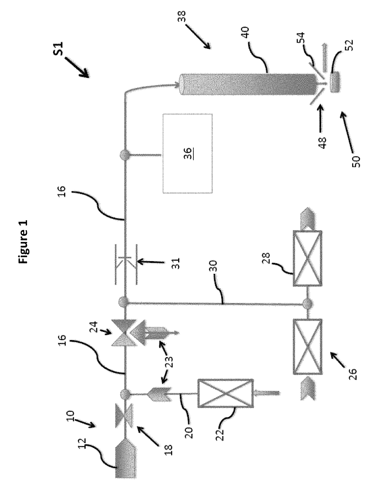
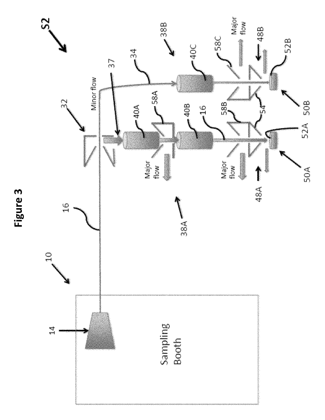
[0016]The present invention relates to an aerosol collection system comprising an inlet portion configured to receive a gaseous fluid containing water vapor and aerosol particles. A primary passage in fluid communication with the inlet portion is configured to channel a flow of the gaseous fluid therethrough. An outlet portion in fluid communication with the primary passage is provided. A sample collection region is configured to receive from the outlet portion the aerosol particles, wherein the aerosol particles are impacted onto a layer of ice in the sample collection region. The system preferably includes at least one laminar flow chilled passage operably associated with the primary passage and configured to cool the gaseous fluid flow to a temperature sufficient to condense the water vapor passing therethrough. A first portion of the water vapor condenses onto the aerosol particles and thereby increases aerodynamic diameter of the aerosol particles. A second portion of the water vapor condenses on an interior surface of the laminar flow chilled passage. In some embodiments, the outlet portion comprises an acceleration nozzle configured to increase velocity of the aerosol particles for impaction onto the layer of ice.
[0020]In some implementations, the system includes a secondary passage in fluid communication with the size selection impactor. Aerosol particles having a diameter greater than a preselected size flow into the secondary passage. In some implementations, the system comprises at least a second laminar flow chilled passage operably associated with the secondary passage and configured to cool the gaseous fluid flow in the secondary passage to a temperature sufficient to condense the water vapor. A portion of the water vapor condenses onto the aerosol particles and thereby increases an aerodynamic diameter of the aerosol particles. Another portion of the water vapor condenses on an interior surface of the second laminar flow chilled passage. In some implementations, the system further comprises a second flow dividing baffle operably associated with the second laminar flow chilled passage and configured to duct liquid water on the interior surface of the second laminar flow chilled passage away from the secondary passage.

Problems solved by technology

Ice impaction also obviates the need to extract a collected sample from a solid surface, e.g., such as a filter, or metal or silicon impaction surface which results in loss and / or damage to the sample.

Method used


Image

  • Aerosol collection system and method
  • Aerosol collection system and method
  • Aerosol collection system and method

Examples


Embodiment Construction

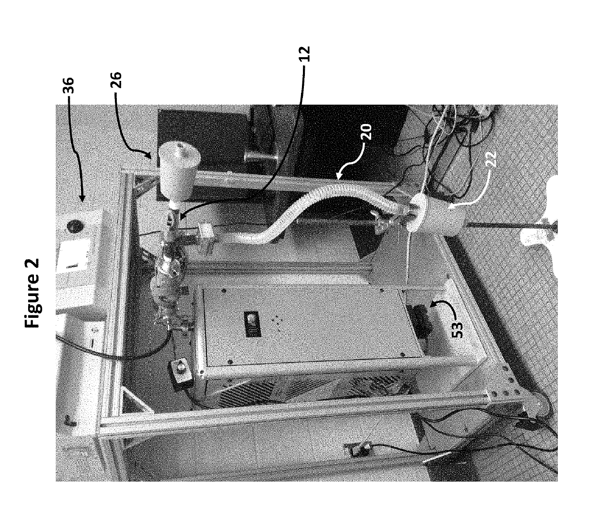
[0033]The present invention relates to systems and methods for collecting and analyzing bioaerosols in a gaseous fluid. In preferred embodiments, the disclosed systems and methods are configured for collecting and analyzing exhaled breath aerosol (EBA) from exhaled breath from a subject, e.g., such as a mammal, preferably a human. In a preferred embodiment, an aerosol collection system includes an inlet portion configured to receive a gaseous fluid containing water vapor and aerosol particles. A primary passage is in fluid communication with the inlet portion and configured to channel a flow of the gaseous fluid therethrough. The system includes one or more laminar flow chilled passage(s) operably associated with the primary passage and configured to cool the gaseous fluid flow to a temperature sufficient to condense the water vapor in the gaseous fluid flow, and additionally grow the aerosol particles to a larger aerodynamic diameter. A small amount of the water vapor condenses ont...


PUM

PropertyMeasurementUnit
temperatureaaaaaaaaaa
volumeaaaaaaaaaa
temperatureaaaaaaaaaa

Abstract

The present invention relates to systems and methods for collecting and analyzing bioaerosols, including exhaled breath aerosol from a subject. The collection system comprises an inlet portion configured to receive a gaseous fluid containing water vapor and aerosol particles. A primary passage for gaseous fluid flow is in fluid communication with the inlet portion and configured to channel the gaseous fluid flow therethrough. An outlet portion is in fluid communication with the primary passage. A sample collection region is provided, which is configured to receive from the outlet portion aerosol particles from the gaseous fluid, wherein the aerosol particles are impacted onto a layer of ice.

Description

STATEMENT REGARDING FEDERALLY SPONSORED RESEARCH OR DEVELOPMENT[0001]This invention was made with government support by the Office of the Director of National Intelligence (ODNI), Intelligence Advanced Research Projects Activity (IARPA), via the Federal Bureau of Investigation under DJF-15-1200-K-0001725. The United States government has certain rights in this invention.CROSS-REFERENCE TO RELATED APPLICATIONS[0002]This application is based on U.S. Provisional Patent Application Ser. No. 62 / 324,254, filed Apr. 18, 2016, titled “Advanced Exhaled Breath Aerosol (EBA) and General Bioaerosol Collection for Infectious Agents & Biomarker Detection Using Cryogenic Impaction,” which application is incorporated herein by reference in its entirety and to which priority is claimed.FIELD OF THE INVENTION[0003]The present invention relates to systems and methods for collecting aerosol particles from a gaseous fluid, and in particular exhaled breath aerosol from exhaled breath from a subject.BACKG...

Claims


Application Information

Patent Timeline
Patent Type & Authority Patents(United States)
IPC IPC(8): G01N1/22G01N1/42A61B5/08A61B5/097G01N33/497G01N15/00
CPCA61B5/097A61B5/082G01N33/497G01N1/2208G01N1/42G01N2015/0026G01N2001/2223G01N2001/2244G01N2033/4975G01N2001/2282
Inventor MILTON, DONALD K.YOUSSEFI, SOMAYEHHERING, SUSANNE V.LEWIS, GREGORY S.
Owner AEROSOL DYNAMICS INC
Why Eureka
Try Eureka