
Method and system for processing images from a remote image detector

a remote image and detector technology, applied in image enhancement, image analysis, instruments, etc., can solve the problems of not using advanced image-processing methods to improve their imagery, chromatic aberration, field curvature, distortion, etc., to reduce noise, improve image quality, and remove image blur

Active Publication Date: 2019-12-10
MICRO BIZ VENTURES
View PDF4 Cites 0 Cited by
  • Summary
  • Abstract
  • Description
  • Claims
  • Application Information

AI Technical Summary

Benefits of technology

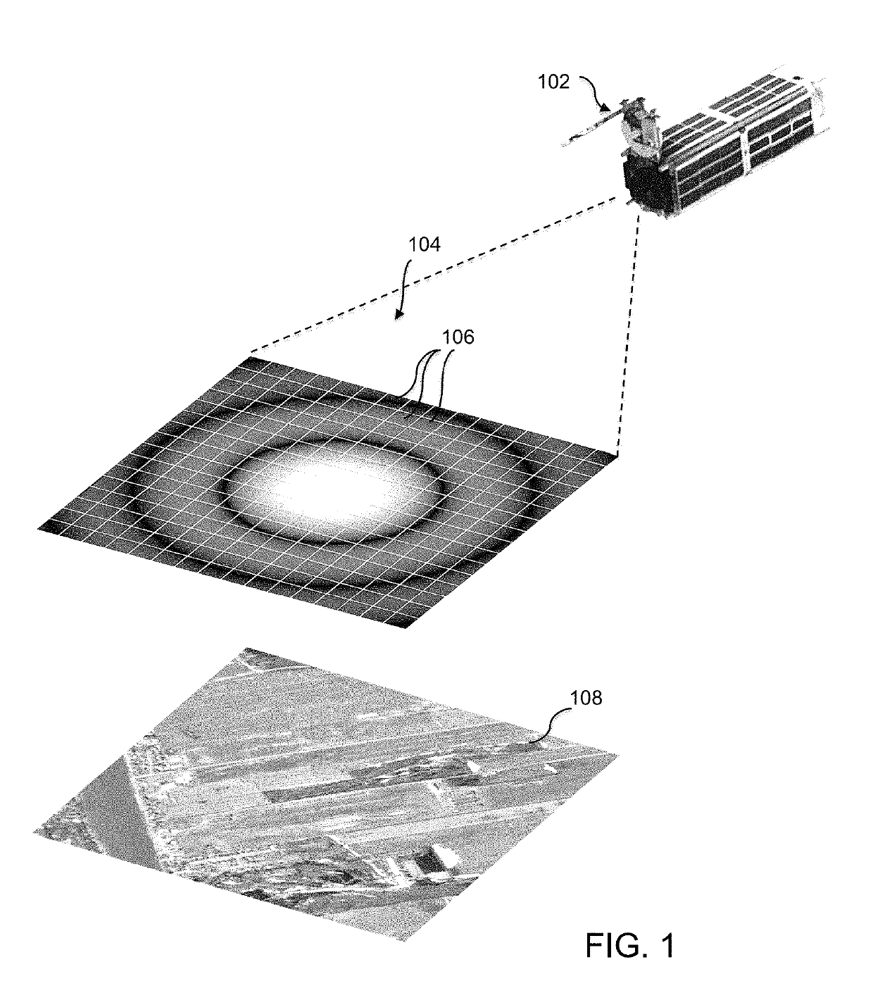
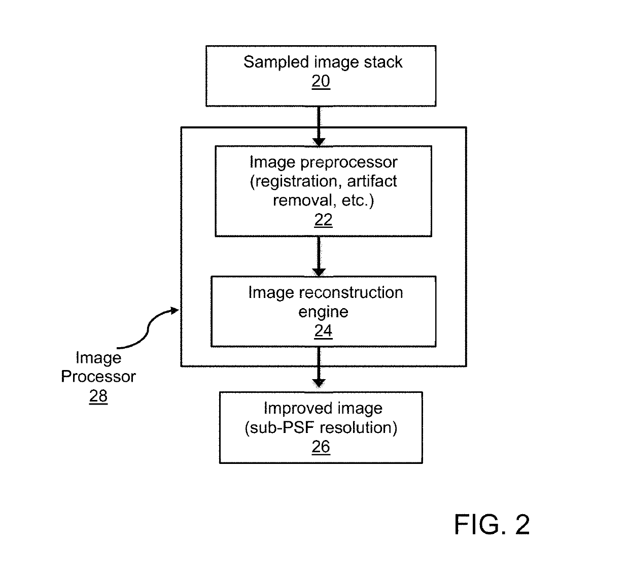
The invention provides a method and system for improving the quality of images collected from rapidly moving platforms, such as satellites or vehicles, by removing image blur and reducing noise. The method involves collecting well-sampled data and applying advanced image processing algorithms, such as deconvolution or the PIXON® method. An image processor receives a stack of image samples and processes them using these algorithms to produce an improved image that is displayed on a display device. This invention has a wide range of applications, including diffraction-limited satellite imaging of the Earth.

Problems solved by technology

There are many commercial and military applications, however, that have not yet employed advanced image-processing methods to improve their imagery.
Major challenges facing remote sensing and imaging applications are spatial resolution and spectral fidelity.
Photographic issues, such as spherical aberrations, astigmatism, field curvature, distortion, and chromatic aberrations are well-known problems that must be dealt with in sensor / imaging applications.
Providing images with very large scale factors, which also have resolution tolerances of inches, poses a challenge to even the most robust imaging system.
On the other hand, if the system provides a larger FOV, the system is going to employ “larger” pixels (greater solid angle per pixel) for maximum coverage, with a resulting a decrease in spatial resolution.
As with the larger military intelligence satellites, these images of Earth from space are generally limited in their spatial resolution by diffraction, and further, since the cameras in such satellites are designed to meet diffraction limits, the signal-to-noise per pixel is largely the same from application to application (the solid angle subtended by a pixel times the telescope aperture size, i.e., the system étendue, is the same in nearly all applications).
However, the fact that smaller telescopes are generally less expensive means that they usually have less sophisticated pointing systems.

Method used


Image

  • Method and system for processing images from a remote image detector
  • Method and system for processing images from a remote image detector
  • Method and system for processing images from a remote image detector

Examples


Embodiment Construction

[0020]In an exemplary embodiment, a method and system for enhancing the quality of images of, or images obtained from, moving objects combines principles of well-sampled imaging data with advanced image reconstruction algorithms to improve spatial resolution of the image. In general, the method and system are applicable in cases where there is relative movement between the location of the image detector and the object to be images. The relative movement may arise from the positioning of the image detector on a satellite (travelling at high speeds on the order of 5,000 to over 20,000 miles per hour, depending on orbit altitude), surveillance aircraft (manned or unmanned, ranging from the low 100's of miles per hour up to supersonic speeds), or other platform located at a high altitude, where the image detector is directed toward an object, either stationary, such as a building or other structure, or an object that is moving at different speed relative to that platform, such as a vehi...


PUM


Abstract

A method and system for enhancing spatial resolution of an image of an object includes using an image detector with a sensor array of pixels configured for extended dynamic range detection. Multiple image sample are collected to assemble a stack of image samples and input into an image processor for processing using an image reconstruction engine to generate a single output image from the stack. In a preferred embodiment, the image reconstruction engine executes the Pixon method for image reconstruction.

Description

RELATED APPLICATIONS[0001]This application claims the benefit of the priority of U.S. Provisional Application No. 62 / 358,925, filed Jul. 6, 2016, which is incorporated herein by reference in its entirety.FIELD OF THE INVENTION[0002]The present invention relates to a method and system for enhancing the quality of images obtained from a satellite or other image detector that is remotely located from the imaged object.BACKGROUND OF THE INVENTION[0003]The improvement of images using advanced image-processing techniques, for example, those described by Puetter et al. in “Digital Image Reconstruction: Deblurring and Denoising”, Ann. Rev. Astron. &Astrophys., 43, pp. 139-194 (2005), has advanced considerably over the last several decades, and such techniques are routinely applied to high-value data, such as satellite observations (Metcalf et al., 1996; Lawrence et al, 2007; Wilson et al., 2015) and astronomical surveys (Hiltner et al., 2003). There are many commercial and military applicat...

Claims


Application Information

Patent Timeline
Patent Type & Authority Patents(United States)
IPC IPC(8): G06T3/40H04N19/182G06T5/50
CPCG06T5/50G06T3/4053H04N19/182G06T2207/10032G06T2207/20208
Inventor PUETTER, RICHARD C.
Owner MICRO BIZ VENTURES
Learn More