Input termination circuits for high speed receivers

a high-speed receiver and input termination technology, applied in the field of communication systems and electrical circuits, can solve the problems of large bandwidth, limited popular applications, and small amount of data transferred, and achieve the effect of stable circuit bandwidth, constant peaking, and stable circuit bandwidth

Active Publication Date: 2019-12-10
MARVELL ASIA PTE LTD
View PDF4 Cites 2 Cited by
  • Summary
  • Abstract
  • Description
  • Claims
  • Application Information

AI Technical Summary

Benefits of technology

[0009]It is to be appreciated that embodiments of the present invention provide many advantages over conventional techniques. Among other things, by stabilizing output impedance of an input termination circuit, bandwidth of the circuit is stabilized and kept substantially constant. For example, stabilized circuit bandwidth is illustrated in FIG. 9, where substantially constant peaking is achieved across different attenuation settings (i.e., translating to substantially constant bandwidth). In comparison, for various conventional input termination circuits, peaking changes at different attenuation settings, thereby resulting in bandwidth degradation. In comparison to conventional designs, input termination circuits according to the present invention improve bandwidth at comparable power budget levels. For example, input termination circuits described herein can be used in SerDes receivers where a high linearity is important. Among other things, high bandwidth for SerDes receivers improves signal to noise ratio (SNR) and Bit Error Rate (BER) of the communication link.
[0010]Embodiments of the present invention can be implemented in conjunction with existing systems and processes. For example, input termination circuits according to the present invention can be manufactured using existing manufacturing processes. Additionally, embodiments of the present invention can be utilized in existing receivers. There are other benefits as well.

Problems solved by technology

In the early days of the Internet, popular applications were limited to emails, bulletin board, and mostly informational and text-based web page surfing, and the amount of data transferred was usually relatively small.
Today, Internet and mobile applications demand a huge amount of bandwidth for transferring photo, video, music, and other multimedia files.
Over the past, various types of conventional input termination circuits have been used, but unfortunately they have been inadequate.

Method used


Image

  • Input termination circuits for high speed receivers
  • Input termination circuits for high speed receivers
  • Input termination circuits for high speed receivers

Examples


Embodiment Construction

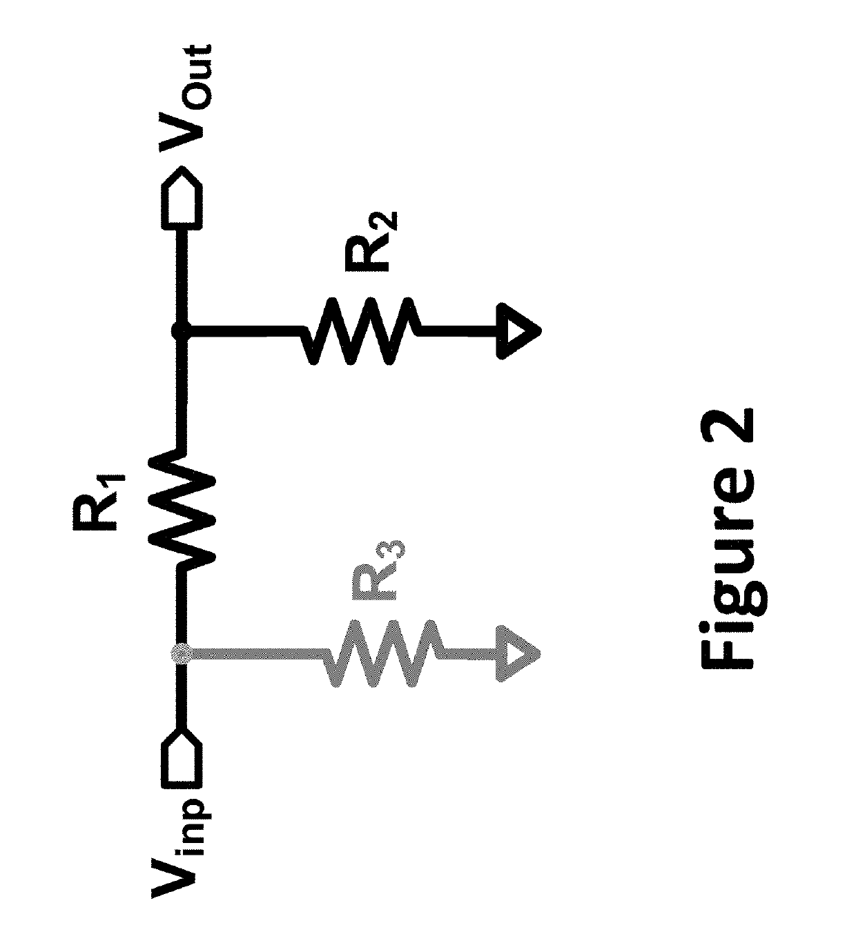
[0022]The present invention is directed to communication systems and electrical circuits. According to an embodiment, an input termination circuit includes a first attenuation resistor and a second attenuation resistor. The resistance values of these two resistors are adjusted in opposite directions to maintain a stable output impedance and bandwidth. There are other embodiments as well.

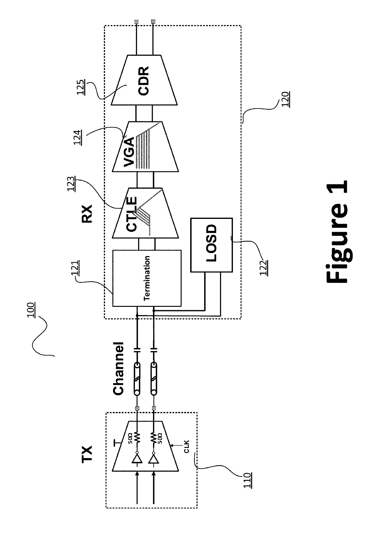
[0023]As mentioned above, input termination circuits are an important aspect of receiver implementation. FIG. 1 is a simplified diagram illustrating a communication system according to embodiments of the present invention. This diagram is merely an example, which should not unduly limit the scope of the claims. One of ordinary skill in the art would recognize many variations, alternatives, and modifications. For example, input termination block 121 is implemented as a part of the receiver section 120. In certain embodiments, receiver section 120 as shown is referred to as an analog front end (AFE) se...


PUM


Abstract

The present invention is directed to communication systems and electrical circuits. According to an embodiment, an input termination circuit includes a first attenuation resistor and a second attenuation resistor. The resistance values of these two resistors are adjusted in opposite directions to maintain a stable output impedance. There are other embodiments as well.

Description

CROSS-REFERENCES TO RELATED APPLICATIONS[0001]This application is a divisional of and claims priority to U.S. patent application Ser. No. 16 / 101,286, filed on Aug. 10, 2018, commonly assigned and incorporated by reference herein for all purposes.BACKGROUND OF THE INVENTION[0002]The present invention is directed to communication systems and electrical circuits.[0003]Over the last few decades, the use of communication networks exploded. In the early days of the Internet, popular applications were limited to emails, bulletin board, and mostly informational and text-based web page surfing, and the amount of data transferred was usually relatively small. Today, Internet and mobile applications demand a huge amount of bandwidth for transferring photo, video, music, and other multimedia files. For example, a social network like Facebook processes more than 500 TB of data daily.[0004]In high speed communication applications, an important aspect is to process received signals at the receiver...

Claims


Application Information

Patent Timeline
Patent Type & Authority Patents(United States)
IPC IPC(8): H03K19/00H04L25/02H04L25/03H04L1/20H04B1/18
CPCH04L25/0292H04L25/0278H04L25/03878H04B1/18H04L1/20
Inventor FOREY, SIMONNAGULAPALLI, RAJASEKHARMISHRA, PARMANAND
Owner MARVELL ASIA PTE LTD
Why Eureka
Try Eureka