Compton camera system and method for detecting gamma radiation

a camera system and gamma radiation technology, applied in the field of gamma ray source imaging, can solve the problems of short life of radioelements used for pets, high cost, and limited application of compton cameras in the present day, and achieve the effect of reducing noise, and reducing the cost of gamma radiation detection

Active Publication Date: 2019-12-17
ILTIS ALAIN
View PDF4 Cites 0 Cited by
  • Summary
  • Abstract
  • Description
  • Claims
  • Application Information

AI Technical Summary

Benefits of technology

[0023]Advantageously, the input face and the output face of the scintillator plate being coupled to the photodetector array are polished and the coupling between said faces and the photodetector array is made by a media of index n less than 1.5 to arrange a total reflection angle. In this case, a double reading of the same event is realized, which improves reconstruction and reduces noise.

Problems solved by technology

But the radioelements used for PET have a short life and are therefore costly.
But applications of the Compton camera these days are limited by its cost, the high level of noise and the difficulty in getting precise reconstructions.
Techniques for processing Compton scattering have to date enjoyed limited success, since to function Compton cameras need a precise location of at least two localized events in two separate places, for example on at least two plates (plate 1 & plate 2) and precise measuring of the energy deposited at each place on each plate.
Compton cameras made with semi-conductors have the following problems: First, the stopping ability of semi-conductor crystals is low.
These crystals must be segmented, each pixel being read separately, and this increases the cost of the system.
The second problem consists of the cost of the crystal functionalized at cm3 being high (about 2000$ / cm3) which limits cameras in small systems.
Another problem of Compton cameras made in this way is that the time response of semi-conductors is slow, over 10 ns.
However, many parasite events are measured during the measuring of a Compton event, meaning that there is substantial noise.

Method used


Image

  • Compton camera system and method for detecting gamma radiation
  • Compton camera system and method for detecting gamma radiation
  • Compton camera system and method for detecting gamma radiation

Examples


Embodiment Construction

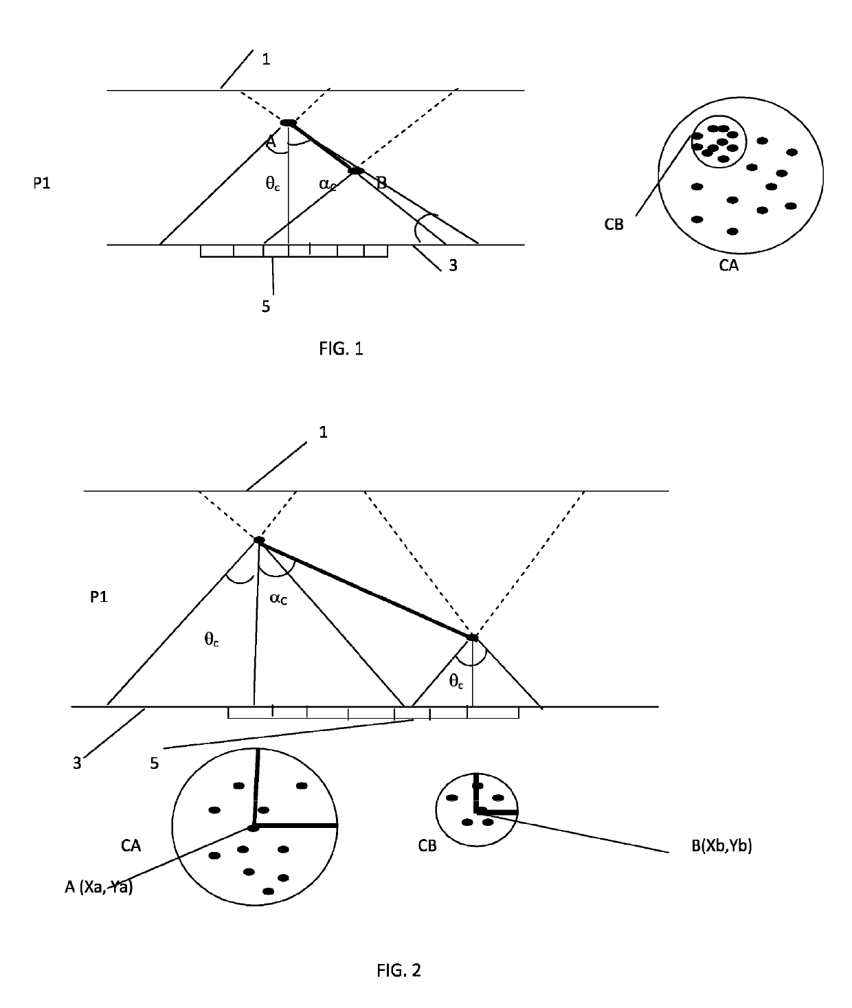
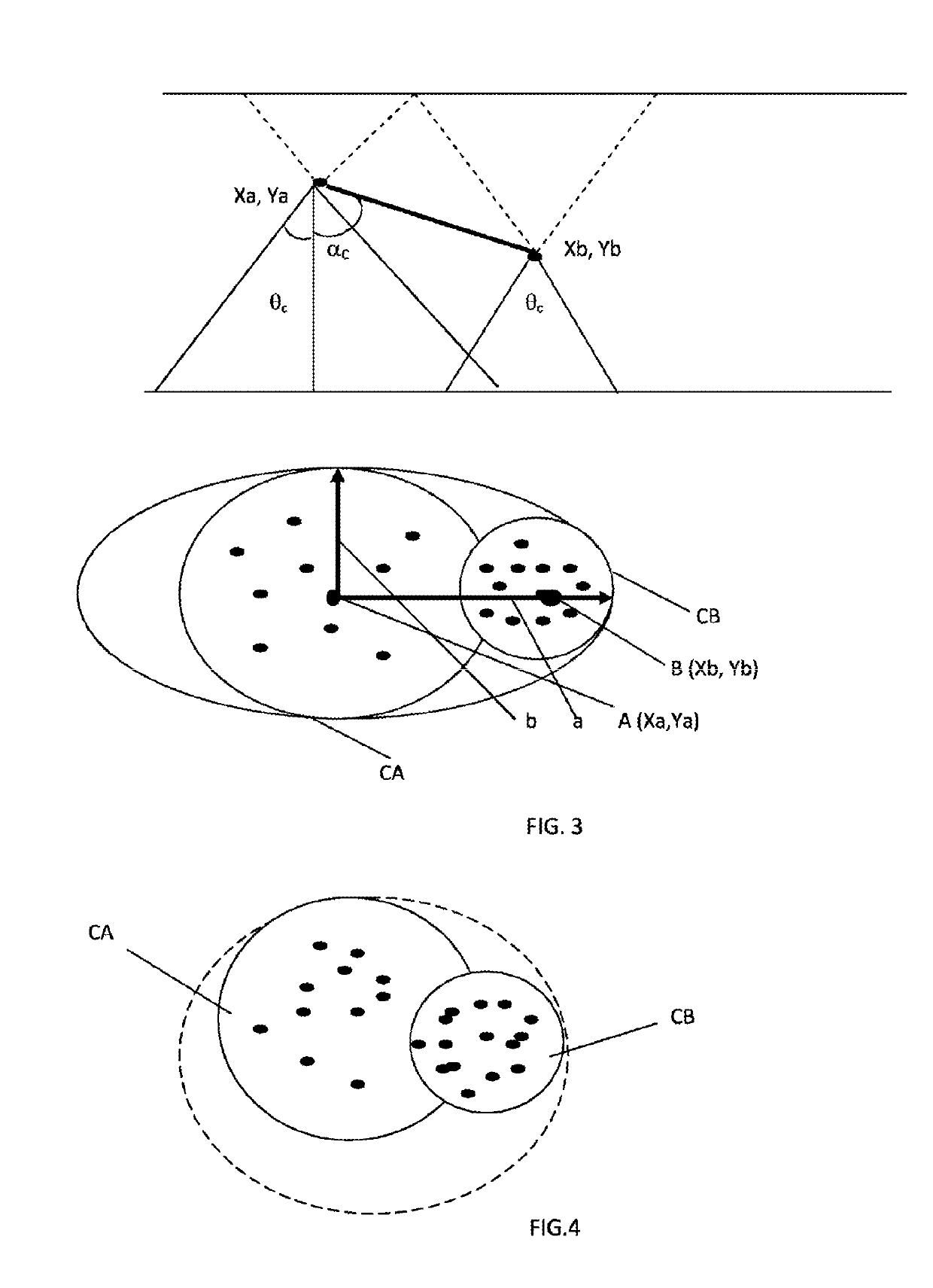
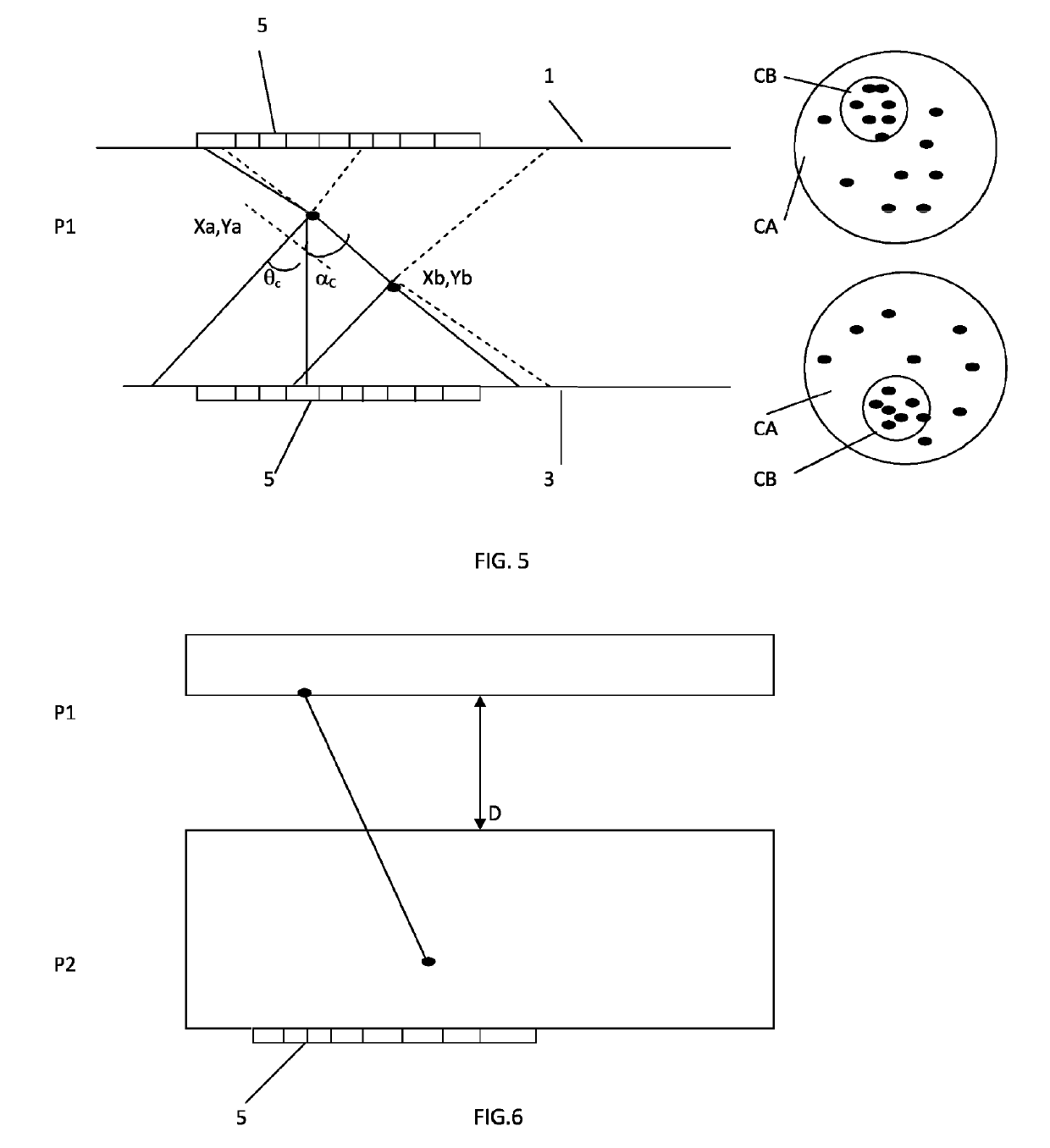
[0020]The invention relates to a system for detecting gamma radiation, of Compton camera type, comprising a source of gamma radiation, at least one rapid scintillator plate P1 whereof the rise time to light peak is less than 1 ns, having a thickness greater than or equal to 5 mm, equipped with an array of segmented photodetectors and dedicated rapid reading micro-electronics; the system is characterized in that it is capable of measuring the spatiotemporal coordinates (X, Y, Z, T) and the energy E in at least two successive positions of a gamma photon when said photon undergoes Compton deviation at a first point A before being absorbed at a second point B, by recognizing circles of unscattered photons corresponding to each scintillation interaction.

[0021]According to the invention, the system for detecting gamma radiation, of Compton camera type, is characterized in that it comprises a single scintillator plate P1 having a thickness greater than or equal to the average free path of ...


PUM


Abstract

A Compton camera system and method for detecting gamma radiation, comprising a gamma radiation source, at least one fast scintillator plate P1 of which the rise time to peak light is less than 1 ns, having a thickness greater than or equal to 5 mm, equipped with an array of segmented photodetectors (5) and a dedicated fast-reading microelectronic means. The system is characterised in that it is capable of measuring the spatial and temporal coordinates (X, Y, Z, T) and energy E at at least two successive positions of a gamma photon when said photon undergoes Compton scattering at a first point A before being absorbed at a second point B, by recognising circles of non-scattered photons corresponding to each scintillation interaction. The system has a module for estimating a valid Compton event. The detection system has two scintillator plates P1 and P2.

Description

TECHNICAL FIELD OF THE INVENTION[0001]The invention relates to gamma ray source imaging. More particularly, the invention relates to a system for detecting gamma rays of Compton camera type for reconstructing an image of the gamma sources, precisely measuring the spatiotemporal coordinates and their energies when said photons undergo Compton deviation. The invention further relates to use of the detection system in the fields particularly of astronomy, nuclear industry and medicine. The invention further relates to the processing of the Compton effect in temporal cameras.STATE OF THE PRIOR ART[0002]At the present time, gamma ray (>30 KeV) sources imaging is essentially performed for medical diagnosis purposes based on two techniques: PET and SPECT. SPECT is based on scintigraphy and produces images and reconstructions in three dimensions of organs and their metabolism by means of an array of gamma cameras revolving around a patient. SPECT can use several energies of gamma rays, b...

Claims


Application Information

Patent Timeline
Patent Type & Authority Patents(United States)
IPC IPC(8): G01T1/20G01T1/164G06T7/10A61B6/02
CPCG01T1/2018G01T1/1647G01T1/1642A61B6/02G06T7/10G01T1/2914
Inventor ILTIS, ALAINSNOUSSI, HICHEM ROBERT RENÉ
Owner ILTIS ALAIN
Why Eureka
Try Eureka