Light source with diffractive outcoupling

a light source and diffractive outcoupling technology, applied in the field of illumination devices, can solve the problems of difficult to accommodate, mechanical instable, cumbersome attachment to the luminescent concentrator rod, etc., and achieve the effect of improving outcoupling

Active Publication Date: 2020-01-21
SIGNIFY HLDG BV
View PDF20 Cites 0 Cited by
  • Summary
  • Abstract
  • Description
  • Claims
  • Application Information

AI Technical Summary

Benefits of technology

[0007]It is an object of the present invention to mitigate this problem, and to provide an illumination device with a concentrating wavelength converter with improved out-coupling.
[0012]However, the invention is based on the realization that in a situation where the angle of incidence on a surface is within a limited range, a combination of refraction and diffraction may provide a superior out-coupling from that surface. Tests indicate that for a typical concentrator, approximately 45% more light may be extracted from the exit surface compared to a conventional concentrator.
[0015]The refractive index of the material forming the structured layer is equal to or greater than nconv−0.3, where nconv is the index of refraction of the material forming the wavelength converter. The index of refraction of the material forming the structured layer is preferably equal to or greater than nconv−0.2, more preferable equal to or greater than nconv−0.1. Even more preferably, a difference between an index of refraction of the structured layer and the index of refraction of the wavelength converter is equal to or less than 0.1, or that the respective refractive indexes are equal. In case the refractive index of the material forming the structured layer is much lower than that of the luminescent material, converted light with certain angles of incidence cannot enter the structured layer because of TIR at the interface of the wavelength converter and the structured layer, and hence cannot be outcoupled; in other words reflection in an interface between the wavelength converter and the structured layer is avoided. Furthermore, the index of refraction of the material of the structured layer is preferably not much higher than the index of refraction of the wavelength converter, because otherwise Fresnel reflection at the interface between the wavelength converter and the structured layer diminishes the amount of light that can enter the structured layer.
[0016]The structured layer may be formed by a sol-gel material containing high-index nano-particles. Alternatively, the structured layer may be formed by a transparent polymer containing high-index nano-particles. In this case, the transparent polymer may be a silicone. When modified with nano-particles, a high index silicone layer may be more stable than nano-particles contained in regular organic polymers. Also, a silicone based material is not as sensitive to layer thickness and related cracking effects, meaning that relatively thick and flexible layers can be replicated.

Problems solved by technology

A problem with such luminescent concentrators is effective out-coupling.
A disadvantage of such a device is that it is cumbersome to attach it to the luminescent concentrator rod and mechanically instable.
Another issue when using a CPC is that the étendue is enlarged by a factor n2 (where n is the refractive index of the CPC material).
This means that, for a given étendue of the application (e.g. projector), the rod should be made smaller, which in turn means that it is more difficult to accommodate enough LEDs at the sides and leads to additional bottlenecks such as thermal limits due to the reduced cooling area.
However, still a large amount of light (up to 40%) will not escape from the converter.

Method used


Image

  • Light source with diffractive outcoupling
  • Light source with diffractive outcoupling
  • Light source with diffractive outcoupling

Examples


Embodiment Construction

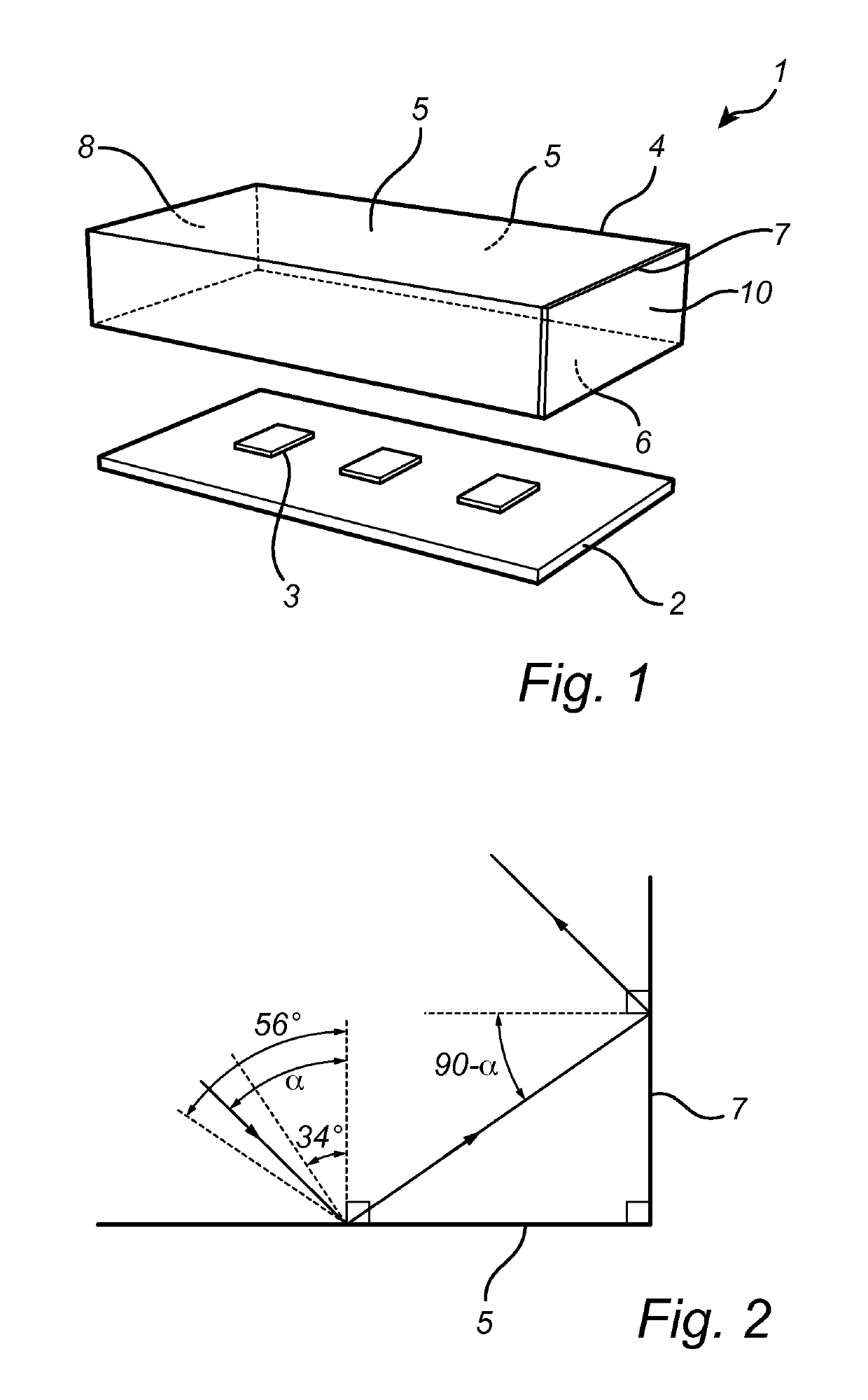
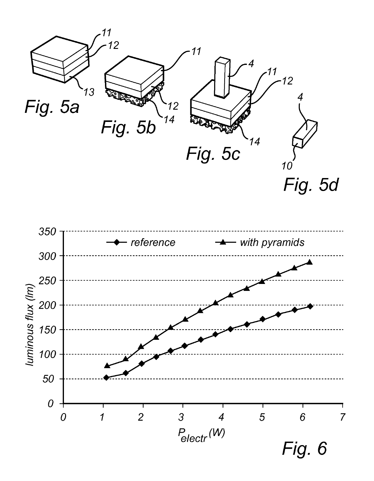
[0027]FIG. 1 is a perspective view of a light emitting device 1 according to an embodiment of the invention, the light emitting device 1 comprises a substrate 2, such as a PCB, carrying a plurality (here three) solid state light sources 3, and a concentrating wavelength converter 4.

[0028]The solid state light source may be a Light Emitting Diode (LED), a Laser Diode or Organic Light Emitting Diode (OLED), a plurality of LEDs or Laser Diodes or OLEDs or an array of LEDs or Laser Diodes or OLEDs. The LED may in principle be an LED of any color, and is in an embodiment a blue light source producing light source light in the blue color-range which is defined as a wavelength range of between 380 nm and 495 nm.

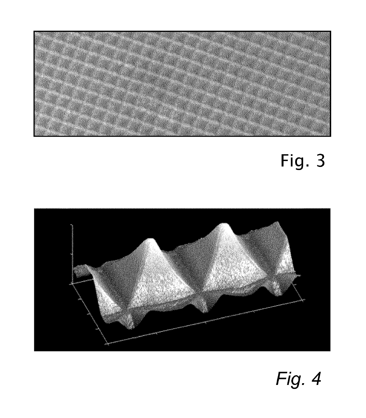
[0029]The wavelength converter is made of a luminescent material. The wavelength converter may comprise either Ce doped Yttrium aluminum garnet (YAG, Y3Al5O12), YGdAG, YGaAG, Lutetium Aluminum-Garnet (LuAG), LuGaAG or LuYAG. YAG, YGdAG, YGaAG, LuAG, LuGaAG and LuYAG are able to have...


PUM

PropertyMeasurementUnit
incidence angleaaaaaaaaaa
angleaaaaaaaaaa
angleaaaaaaaaaa

Abstract

An illumination device comprising a plurality of solid state light sources and a concentrating wave length converter arranged to inject light from said light sources through at least one entrance surface and to extract wave length converted light from at least one exit surface, comprising a structured layer provided on said exit surface, said structured layer having a structure period less than 5 micrometers, thereby enabling out-coupling through the exit surface by a combination of refraction and diffraction. In a situation where the angle of incidence on a surface is within a limited range, a combination of refraction and diffraction may provide a superior out-coupling from that surface.

Description

CROSS-REFERENCE TO PRIOR APPLICATIONS[0001]This application is the U.S. National Phase application under 35 U.S.C. § 371 of International Application No. PCT / EP2016 / 059220, filed on Apr. 26, 2016, which claims the benefit of European Patent Application No. 15187285.0, filed on Sep. 29, 2015. These applications are hereby incorporated by reference herein.FIELD OF THE INVENTION[0002]The invention relates to an illumination device comprising a plurality of solid state light sources and a concentrating wave length converter arranged to inject light from said light sources through at least one entrance surface and to extract wave length converted light from at least one exit surface.BACKGROUND OF THE INVENTION[0003]Solid state light sources, such as LEDs, have been established as an energy efficient alternative to conventional light sources. In some high power applications, e.g. spot lights and image projection, it has been proposed to couple light from several light sources (e.g. LEDs) ...

Claims


Application Information

Patent Timeline
Patent Type & Authority Patents(United States)
IPC IPC(8): H01L33/50F21V8/00H01L25/075G02B19/00G03B21/20F21Y115/10
CPCH01L25/0753H01L33/505G02B19/0066G02B6/0003G02B19/0009F21Y2115/10G02B6/0068G02B6/0053G03B21/204
Inventor DE BOER, DIRK KORNELIS GERHARDUSVERSCHUUREN, MARCUS ANTONIUSSOUREN, ANNEJAGT, HENDRIK JOHANNES BOUDEWIJN
Owner SIGNIFY HLDG BV
Why Eureka
Try Eureka