Prosthetic heart valve

a heart valve and prosthesis technology, applied in the field of prosthesis, can solve the problems of increasing total stroke volume and reducing cardiac output, and achieve the effect of facilitating one-way blood flow

Active Publication Date: 2020-03-03
CARDIOVALVE LTD
View PDF948 Cites 49 Cited by
  • Summary
  • Abstract
  • Description
  • Claims
  • Application Information

AI Technical Summary

Benefits of technology

[0046]a plurality of elongate projections, each of the projections extending from an upstream extremity of a respective first-row cell, and terminating in a nub that facilitates snaring of the projection.
[0253]the prosthetic valve has a compressed state in which the prosthetic valve is transluminally deliverable to the native heart valve, and is expandable at the native heart valve into an expanded state in which the valve member facilitates one-way blood flow through the lumen,

Problems solved by technology

Regurgitation of blood from the ventricle into the atrium results in increased total stroke volume and decreased cardiac output, and ultimate weakening of the ventricle secondary to a volume overload and a pressure overload of the atrium.

Method used


Image

  • Prosthetic heart valve
  • Prosthetic heart valve
  • Prosthetic heart valve

Examples


Embodiment Construction

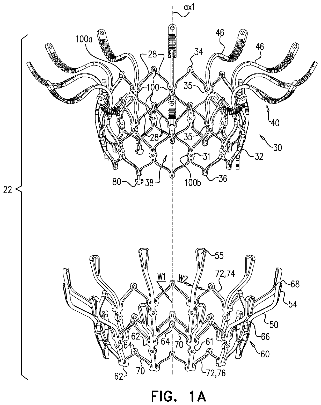
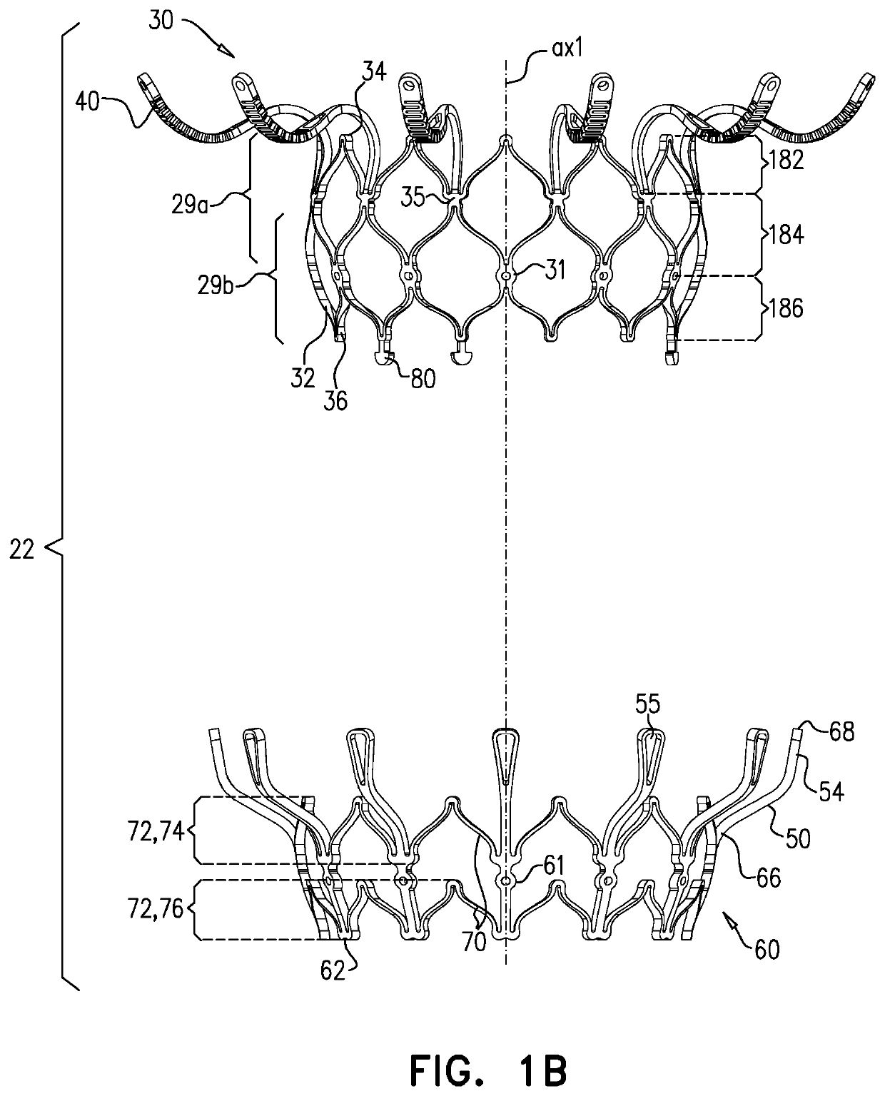
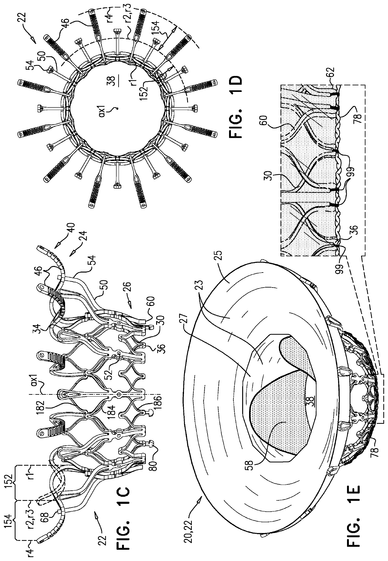
[0297]Reference is made to FIGS. 1A-E and 2, which are schematic illustrations of an implant 20 and a frame assembly 22 of the implant, in accordance with some applications of the invention. Implant 20 serves as a prosthetic valve for use at a native heart valve of a subject—typically the mitral valve. Implant 20 has a compressed state for minimally-invasive (typically transluminal, e.g., transfemoral) delivery, and an expanded state into which the implant is transitioned at the native heart valve, and in which the implant provides prosthetic valve functionality. Implant 20 comprises frame assembly 22, flexible sheeting 23, and a valve member, such as prosthetic leaflets 58.

[0298]FIGS. 1A-E show implant 20 and frame assembly 22 in the expanded state. For clarity, FIGS. 1A-D show frame assembly 22 alone. FIG. 1A shows an isometric exploded view of frame assembly 22, and FIG. 1B shows a side exploded view of the frame assembly. FIGS. 1C and 1D are side- and top-views, respectively, of...


PUM

PropertyMeasurementUnit
transverse diameteraaaaaaaaaa
lengthaaaaaaaaaa
lengthaaaaaaaaaa

Abstract

A frame assembly includes a valve body, a plurality of arms that each extend radially outward from the valve body to a respective arm-tip, and a plurality of ventricular legs that are coupled to the valve body and that extend radially outward from the valve body and toward the plurality of arms. A liner lines the lumen. Prosthetic leaflets are attached to the liner within the lumen. A first sheet of flexible material is attached to the plurality of arms. A second sheet of flexible material is attached to the first sheet and extends radially inwards and downstream, and is attached to the valve body. The first sheet, the second sheet, and the liner define an inflatable pouch therebetween. The apparatus defines a plurality of windows from the lumen into the pouch.

Description

CROSS-REFERENCES TO RELATED APPLICATIONS[0001]The present application is a Continuation-In-Part of U.S. patent application Ser. No. 15 / 668,559 to Iamberger et al., filed Aug. 3, 2017, and entitled “Prosthetic heart valve,” which is incorporated herein by reference.FIELD OF THE INVENTION[0002]Some applications of the present invention relate in general to valve replacement. More specifically, some applications of the present invention relate to prosthetic valves for replacement of a cardiac valve.BACKGROUND[0003]Ischemic heart disease causes regurgitation of a heart valve by the combination of ischemic dysfunction of the papillary muscles, and the dilatation of the ventricle that is present in ischemic heart disease, with the subsequent displacement of the papillary muscles and the dilatation of the valve annulus.[0004]Dilation of the annulus of the valve prevents the valve leaflets from fully coapting when the valve is closed. Regurgitation of blood from the ventricle into the atriu...

Claims


Application Information

Patent Timeline
Patent Type & Authority Patents(United States)
IPC IPC(8): A61F2/24B29C39/00B29C39/10B29K83/00B29L31/40
CPCA61F2/2418B29C39/10A61F2/2436A61F2/2409A61F2/24B29C39/003B29K2083/00A61F2/2415A61F2/2427A61F2250/0003A61F2230/0065A61F2240/001A61F2220/0025B29L2031/40
Inventor IAMBERGER, MENIBAUM, AVIRAMHARITON, ILIAKASIMOV, YELENA
Owner CARDIOVALVE LTD
Why Eureka
Try Eureka