Seal panel for a gas turbine engine

a gas turbine engine and seal panel technology, applied in the direction of machines/engines, efficient propulsion technologies, mechanical equipment, etc., can solve the problems of increased compressor speed and air pressure provided to the seal panel, premature wear and potential lifting issues, and increased rearward force, so as to achieve weight saving and reduce the size of the seal panel

Active Publication Date: 2020-03-17
ROLLS ROYCE PLC
View PDF22 Cites 0 Cited by
  • Summary
  • Abstract
  • Description
  • Claims
  • Application Information

AI Technical Summary

Benefits of technology

[0012]Providing a seal panel which a rotor portion and a stator portion in which the rotor portion is a cantilever, allows the seal to be placed closer to the rotor and the size of the seal made smaller, thereby providing a significant weight saving.
[0030]A stiffening member may be included on the seal plate to reduce bending of the seal ring and to concentrate the load in to the failing bolts. The stiffening member may be on the radial outer of the seal ring and may be provided by a flange which extends radially away from the seal plate. The flange may be located towards an axial end of the seal plate. The axial end may be the axial end which is opposite to the attachment end. The radial (or transverse) section of the annular stator portion seal may be substantially u-shaped with one side of the u-shape providing the stiffening member, and the other side of the u-shaped member providing the attachment end.

Problems solved by technology

However, in some instances, the net rearward force may load the bearings to an undesirable level causing premature wear and potential lifting issues.
Thus, the harder and faster the turbine is driven, the greater the rearward force, but the greater the compressor speed and air pressure provided to the seal panel.
Placing the seal at such a radial extent requires a large seal due to the resultant circumferential length.
When using a large conventional seal this inevitably comes with a weight penalty.

Method used


Image

  • Seal panel for a gas turbine engine
  • Seal panel for a gas turbine engine

Examples


Embodiment Construction

[0038]Unless otherwise stated, in the following description the terms axial and radial will generally have reference to the principal axis of rotation, which in the described in disclosure is the principal axis of the engine. Terms such as upstream and downstream, fore and aft, are used in view of the general direction of air flow through the engine from fan at the front, the nozzle at the rear.

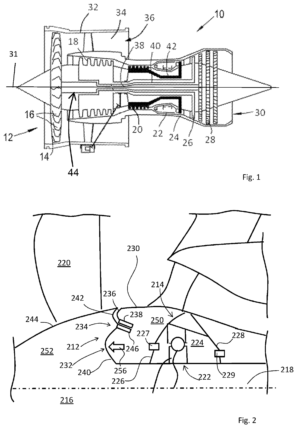
[0039]FIG. 2 shows a schematic partial longitudinal section of a gas turbine engine having a seal panel 212, a shaft support system 214 by which a shaft 216 is axially and rotatably retained on the central or principal axis of rotation 218 of the engine, and a fan 220.

[0040]The shaft is retained on the principal axis of the engine in normal use in part by a bearing arrangement 222 which, in the described example, is a thrust bearing providing axial and radial restraint of the shaft and fan assembly. The bearing arrangement 222 is located within a bearing chamber 224 having fore 226 and aft 22...


PUM


Abstract

Described is a shaft support system for a gas turbine engine comprising: a rotatable fan shaft; first and second support structures extending in parallel from the shaft to a load bearing structure to provide radial location of the shaft within an engine casing, wherein the first support and second support structures include first and second respective mechanical fusible joints; wherein the first fusible joint is a two-stage fuse which partially fails within a first predetermined load range, the second fusible joint fails within a second predetermined load range which is different to the first load range, and the first fusible joint fully fails only when the second fusible joint has failed.

Description

CROSS-REFERENCE TO RELATED APPLICATIONS[0001]This specification is based upon and claims the benefit of priority from UK Patent Application Number 1704045.2 filed on 14 Mar. 2017, the entire contents of which are incorporated herein by reference.TECHNICAL FIELD OF DISCLOSURE[0002]The present disclosure relates to a seal panel for a gas turbine engine. The seal panel provides a seal between a propulsive fan and a forward bearing chamber of the gas turbine engine.BACKGROUND OF DISCLOSURE[0003]FIG. 1 shows a ducted fan gas turbine engine 10 comprising in axial flow series: an air intake 12, a propulsive fan 14 having a plurality of fan blades 16, an intermediate pressure compressor 18, a high-pressure compressor 20, a combustor 22, a high-pressure turbine 24, an intermediate pressure turbine 26, a low-pressure turbine 28 and a core exhaust nozzle 30. A nacelle 32 generally surrounds the engine 10 and defines the intake 12, a bypass duct 34 and a bypass exhaust nozzle 36. The engine has...

Claims


Application Information

Patent Timeline
Patent Type & Authority Patents(United States)
IPC IPC(8): F01D25/16F01D21/08F02C7/28F01D25/28F01D25/24F02C7/06F01D21/04
CPCF01D25/164F01D25/16F01D25/24F01D21/08F02C7/28F02C7/06F01D21/045F01D25/28Y02T50/672F05D2240/55F05D2220/32F05D2260/311F05D2240/50F16C2360/23Y02T50/60
Inventor PHILLIPS, IAIN DAVID MARTIN
Owner ROLLS ROYCE PLC
Why Eureka
Try Eureka