Method for reinforcing anti-engine stall and vehicle

a technology of anti-stalling and anti-engine, which is applied in the direction of machines/engines, electric control, speed sensing governors, etc., can solve the problems of inability to completely prevent the engine from being stalled, inability to control and inability to accurately detect the abnormality of the ckps

Active Publication Date: 2020-03-24
HYUNDAI MOTOR CO LTD +1
View PDF18 Cites 0 Cited by
  • Summary
  • Abstract
  • Description
  • Claims
  • Application Information

AI Technical Summary

Benefits of technology

[0013]Various aspects of the present invention are directed to providing a method for reinforcing anti-engine stall and a vehicle, in which continuous modeling of revolutions per minute (RPM) of an engine is performed based on detection values of a camshaft position sensor (CMPS) and control of the engine is performed using modeling values of RPM of the engine, which are estimated based on the modeling of the RPM of the engine at the time of occurrence of abnormality of a crank position sensor (CKPS), so that it is possible to prevent engine stall that may occur before error diagnosis of the CKPS is confirmed and therefore a diagnostic trouble code is generated and it is possible to prevent engine stall that may occur by applying inaccurate estimation values of RPM in an engine RPM modeling values, which are brought by variation of gear ratios of a crankshaft and a camshaft due to advance / retard movement of the cam, when abnormal phenomenon of the CKPS is detected.
[0019]In an exemplary embodiment of the present invention, the step of performing control before confirmation of abnormality of the CKPS may include: (c-1) identifying display of diagnostic trouble code according to the detection of abnormality of the CKPS with respect to the crankshaft after the engine is activated and controlled, (c-2) determining values of engine control to engine RPM modeling values in the engine RPM modeling generated by the detection values of the CMPS with respect to the camshaft when the diagnostic trouble code is not displayed, (c-3) maintaining the current position of the variable valve timing system at the time of occurrence of abnormality of the CKPS such that cam timing control of operation of the variable valve timing system is maintained after the engine RPM modeling values are estimated, (c-4) controlling the number of rotations of the engine to be higher is performed based on the engine RPM modeling values after the engine RPM modeling values are estimated so that engine stall of the engine is prevented, (c-5) returning the variable valve timing system back to the default position, and (c-6) confirming error diagnosis of the CKPS resulting from identification of display of the diagnostic trouble code based on the fact that the abnormality of the CKPS is maintained during a predetermined time period from the time of detecting abnormality of the CKPS, and maintaining the cam phase control operation of the variable valve timing system in the position at the time of detection of abnormality of the CKPS.
[0021]In an exemplary embodiment of the present invention, the step of performing control of abnormality of the CKPS prevents engine stall by controlling the number of rotations of the engine according to the estimation values of the engine RPM based on the detection values of the CMPS after the error diagnosis of the CKPS is confirmed.
[0023]In an exemplary embodiment of the present invention, the controller may include a map for modeling the number of rotations of the engine (the “engine RPM modeling”), by which the engine RPM modeling is performed based on detection values of the CMPS, wherein the engine RPM modeling estimates engine RPM modeling values from the time when abnormality of the CKPS occurs until the time when a diagnostic trouble code is displayed and wherein the engine RPM modeling values are applied in controlling the number of rotations of the engine to be higher than that at the time when abnormality of the CKPS occurs so that engine stall is prevented.
[0025]The method for reinforcing anti-engine stall, which is applied to the vehicle of the present invention, continuously utilizes detection values of the CMPS and thus implements the following advantages and effects in controlling the cam timing when inaccurate estimation values of RPM is derived by an engine RPM modeling values.
[0026]First, estimation values of the engine RPM based on detection values of the CMPS and an engine RPM modeling values based on the CMPS modeling are associated with each other in controlling the cam timing so that engine control performance is greatly enhanced. Second, since abnormality of the CKPS is divided into occurrence of trouble in the CKPS and a time period before DTC is generated and a time period after DTC is generated, it is possible to effectively prevent engine stall that can be caused before abnormality of the CKPS is diagnosed resulting from generation of DTC. Third, since maintenance of the current position and control of the default for the variable valve timing system are applied together when trouble of the CKPS occurs, it is possible to prevent deterioration of stability of the engine RPM that can be brought by the variable valve timing system applied to the camshaft connected to the crankshaft via a timing chain. Fourth, since reliability of control of the engine timing is enhanced and thus engine stall due to abnormality of the CKPS is prevented, merchantability of the variable valve timing system and the vehicle is greatly enhanced.

Problems solved by technology

However, the cam timing control is an approach that it is difficult to completely prevent the engine from being stalled due to limitation in the manner of diagnosing error of the CKPS.
Furthermore, abnormality of the CKPS can be controlled even after the diagnostic trouble code is generated and then error of the CKPS is confirmed.
For example, structure of connecting a timing chain for a crankshaft and a camshaft fixes speed of the camshaft with the aid of gear ratio between the crankshaft and the timing chain but has a high possibility of occurring variation of the gear ratio at the time when the cam advances / retards, whereby determination of estimation values of the engine RPM using detection values of the CKPS until diagnosis of error of the CKPS is confirmed according to generation of DTC at the time of abnormality of the CKPS may be inaccurate or impossible.
As a result, since inaccurate estimation values of the engine RPM is inevitably used at the time when momentary problem of the CKPS occurs during control of the cam timing, engine stall cannot be completely prevented until the cam returns to its default position.

Method used


Image

  • Method for reinforcing anti-engine stall and vehicle
  • Method for reinforcing anti-engine stall and vehicle
  • Method for reinforcing anti-engine stall and vehicle

Examples


Embodiment Construction

[0036]Reference will now be made in detail to various embodiments of the present invention(s), examples of which are illustrated in the accompanying drawings and described below. While the invention(s) will be described in conjunction with exemplary embodiments, it will be understood that the present description is not intended to limit the invention(s) to those exemplary embodiments. On the contrary, the invention(s) is / are intended to cover not only the exemplary embodiments, but also various alternatives, modifications, equivalents and other embodiments, which may be included within the spirit and scope of the invention as defined by the appended claims.

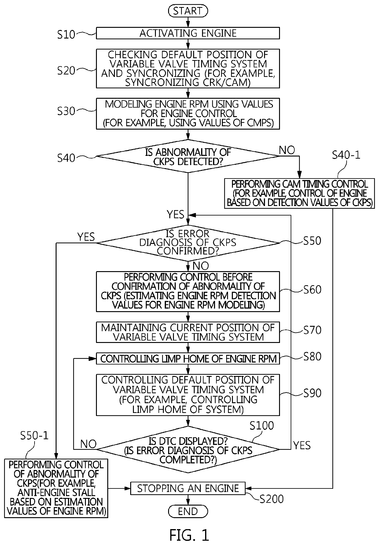
[0037]Referring to FIG. 1, the method is appropriated for reinforcing anti-engine stall when inaccurate estimation values of RPM is derived by an engine RPM modeling values. The method divided into steps of: identifying abnormality of the CKPS in steps S20 to S40 at the time of activation of an engine in step S10; performing cam t...


PUM


Abstract

A method for reinforcing anti-engine stall may include performing a cam timing control for measuring engine speed of an engine wherein when abnormality of a crank position detector is detected by a controller, engine speed of the engine is controlled to be higher than that at the time when the abnormality of crank position detector occurs while maintaining position for cam phase control operation of a variable timing system.

Description

CROSS-REFERENCE(S) TO RELATED APPLICATIONS[0001]The present application claims priority to Korean Patent Application No. 10-2017-0082581, filed on Jun. 29, 2017, the entire contents of which is incorporated herein for all purposes by this reference.BACKGROUND OF THE INVENTIONField of the Invention[0002]The present invention relates to engine stall, and more particularly, to a vehicle in which engine stall prevention (hereinafter referred to as “anti-engine stall”) is reinforced by performing engine control rapidly from the time point when an abnormal phenomenon occurs in a crank position detector.Description of Related Art[0003]In general, unwanted engine stall of an internal combustion engine vehicle is a phenomenon that must be avoided most preferentially.[0004]A typical example of a method of preventing engine stall includes cam timing control using a crank position sensor (hereinafter referred to as CKPS). The cam timing control is implemented by controlling synchronization of t...

Claims


Application Information

Patent Timeline
Patent Type & Authority Patents(United States)
IPC IPC(8): F02D41/00F02D13/02F02D41/22F02D31/00F02D41/14
CPCF02D31/001F02D13/0219F02D41/0002F02D41/222F02D13/02F02D41/0097F02D41/009F02D2041/001F02D2041/227F02D2200/101F02D2041/1433F02D2250/14F02D13/0203F01L1/34F01L2800/11F01L2820/042F01L2820/041
Inventor KIM, SUNG-JOO
Owner HYUNDAI MOTOR CO LTD
Why Eureka
Try Eureka