Vertical door system with ball screw drive

a technology of vertical doors and ball screws, applied in the direction of door/window fittings, wing accessories, wing arrangements, etc., can solve the problems of significant increase in the weight and installation time of the system, catastrophic failure of a lifting mechanism, such as a cable, and achieve the effect of more compact, more light weight and higher energy efficiency

Active Publication Date: 2020-03-31
DOORWALL SYST CORP
View PDF19 Cites 3 Cited by
  • Summary
  • Abstract
  • Description
  • Claims
  • Application Information

AI Technical Summary

Benefits of technology

[0020]The vertical door system of the disclosed embodiments provides a quieter, more compact, more light-weight, and safer alternative to conventional vertical door designs which use springs, cables, straps, hydraulics, belts, counterweights and lift-pin slots. By using a combination of features described herein, e.g., a threaded ball screw powered by a heavy duty direct-drive operator such as a manual or electric motor, and moving slider blocks (both driven and non-driven) which are fastened with pivot pins to sections of the door frame, a vertical door system is provided that improves performance of prior art door systems of this type.
[0021]The disclosed embodiments provide a vertically-operated door system with a higher level of energy efficiency, as an alternative to conventional door designs which use unitary steel tube frames and single weather seals. By using a combination of features such as, for example, but not limited to, a thermally-broken frame, i.e., a frame construction that uses separator materials between interior and exterior portions of the door frame to prevent temperature transfer through the door frame and resulting condensation on the interior portion of the door frame, with or without brush seals, which, inter alia, prevent rodents from infiltrating the opening covered by the door, and a bulb seal, which enables a substantially complete seal at the perimeter to block air and light, with or without insulated foam sections enhancing the thermal performance of the door frame for both heat and cooling. Significant performance enhancement can be achieved over conventional vertical door designs. The thermal efficiencies gained from the use of, but not limited to, these three components, i.e., the thermally-broken frame, bulb seal, and brush seal, provide a higher level of energy efficiency over conventional approaches and thereby enable the end user to spend less on energy while providing a more comfortable environment.

Problems solved by technology

Such systems often employ counterweights which require additional space and which significantly increase the weight and installation time of the system.
Furthermore, the failure of a lifting mechanism, such as a cable, can have catastrophic results.

Method used


Image

  • Vertical door system with ball screw drive
  • Vertical door system with ball screw drive
  • Vertical door system with ball screw drive

Examples


Embodiment Construction

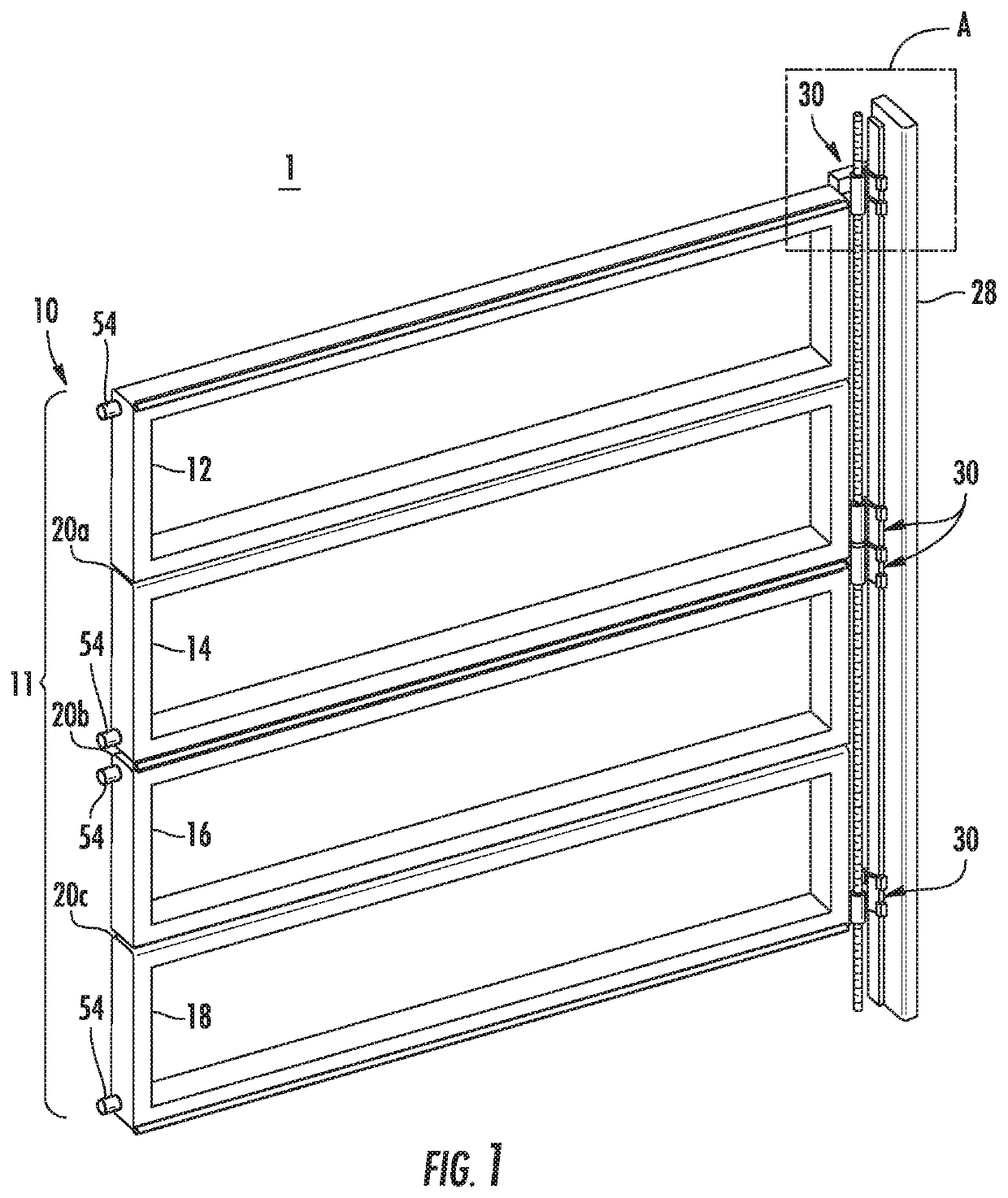
[0058]FIG. 1 is a partial view of a quad-panel vertical door system 1. In the system 1, a door 10 is formed from a frame 11 with four frame sections 12, 14, 16, and 18, which are joined by hinges 20a, 20b, and 20c. The door is configured to open in an upward vertical direction as the frame sections fold together (see, e.g., FIG. 6, discussed below). In particular embodiments, each section of the frame 11 has a panel of insulated glass. The frame 11 is connected to a drive system 13, which will be described in detail below. It is noted that in FIG. 1 for illustration purposes the drive system 13 is shown on the right side of the door. It will be appreciated by those of ordinary skill that the drive system can likewise be positioned only on the left side of the door, or on both sides of the door, depending on the application.

[0059]Each of the frame sections 12, 14, 16, and 18 has a pair of connection members (i.e., pivot pins) 54 extending from opposite sides thereof which are each co...


PUM


Abstract

A vertical door system includes: a door having a door frame, the door frame having at least one frame section; an operator; two vertical supports configured to: (a) be installable on opposite sides of the door opening and (b) support the vertical door, at least one of the vertical supports having: a guide track on a surface of the vertical support facing toward the door opening; and a drive system having: an elongated threaded rod drivable by the operator via a gearing arranged between the operator and the threaded rod; and one or more blocks, each block comprising a guide track connecting portion that connects to a guide track so the connected block is freely movable along the guide track, each block having a through-bore for accepting the threaded rod so that the block is positioned on the threaded rod and is movable along the threaded rod.

Description

CROSS-REFERENCE TO RELATED APPLICATION[0001]This application claims benefit of U.S. Provisional Patent Application Ser. No. 62 / 357,761, filed on Jul. 1, 2016, the entirety of which is incorporated herein by reference.FIELD OF THE INVENTION[0002]The disclosed embodiments relate to a vertical door system. In particular, the disclosed embodiments relate to a vertical door system on which is mounted driven and non-driven blocks which are pivotally-attached to the door frame.BACKGROUND OF THE INVENTION[0003]Conventional vertical door systems use various mechanisms for operating the vertical door between opened and closed positions, such as cables, springs, lift straps, and hydraulic mechanisms. Such systems often employ counterweights which require additional space and which significantly increase the weight and installation time of the system. Furthermore, the failure of a lifting mechanism, such as a cable, can have catastrophic results.SUMMARY OF THE INVENTION[0004]According to a firs...

Claims


Application Information

Patent Timeline
Patent Type & Authority Patents(United States)
IPC IPC(8): E05F15/673E06B3/44E06B3/48E06B3/263E06B3/70E06B3/54E06B3/62E06B3/50E06B3/58
CPCE06B3/44E06B3/483E05F15/673E06B3/5009E06B3/5018E06B3/4407E06B2003/6258E06B3/5807E06B3/5878E06B2003/6223E06B3/549E06B2003/7044E05Y2900/106E05Y2201/718E05Y2201/696E05Y2201/70E06B3/26303E05Y2201/684
Inventor GRACE, JAMES SCOTT
Owner DOORWALL SYST CORP
Why Eureka
Try Eureka