Electric driving apparatus

a technology of electric driving apparatus and rotation sensor, which is applied in the direction of electrical steering, association with control/drive circuit, transportation and packaging, etc., can solve the problems of increasing the likelihood of detection errors, reduce detection errors by rotation sensors, and suppress the reduction in the performance of electric driving apparatus. , the effect of improving the freedom of feeder wires

Active Publication Date: 2020-04-21
MITSUBISHI ELECTRIC CORP
View PDF23 Cites 0 Cited by
  • Summary
  • Abstract
  • Description
  • Claims
  • Application Information

AI Technical Summary

Benefits of technology

[0012]With the electric driving apparatus according to this invention, noise magnetic fields acting on the rotation sensor from the feeder wires, the inverter circuit, and so on, for example, can be blocked by the shield plate. Moreover, the intensity of the magnetic field generated by the sensor magnet is unlikely to decrease in the position of the rotation sensor. As a result, detection errors by the rotation sensor can be reduced, and a reduction in the performance of the electric driving apparatus can be suppressed. Furthermore, the disposal freedom of the feeder wires can be improved, thereby preventing an increase in the size of the electric driving apparatus.

Problems solved by technology

In this type of conventional motor, when a conductor wire through which a current flows, for example, is disposed on the periphery of the magnetic sensor, a noise magnetic field generated by the conductor wire acts on the magnetic sensor, leading to an increase in the likelihood of a detection error occurring when the magnetic sensor detects the magnetism.

Method used


Image

  • Electric driving apparatus
  • Electric driving apparatus
  • Electric driving apparatus

Examples


first embodiment

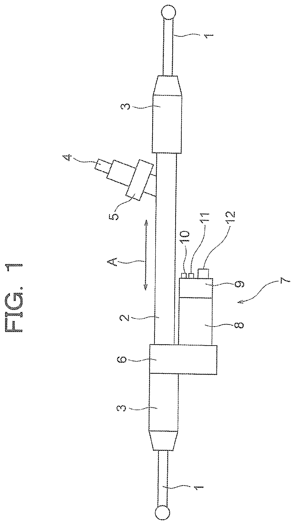
[0031]FIG. 1 is a view showing a configuration of an electric power steering apparatus according to a first embodiment of this invention. The electric power steering apparatus according to this embodiment is an electric power steering apparatus for a vehicle, which is installed in a vehicle such as an automobile, for example. A rack shaft (not shown) housed in a housing 2 is connected between a pair of tie rods 1. Respective connection portions between the tie rods 1 and the rack shaft are housed in rack boots 3 that prevent foreign matter from infiltrating the electric power steering apparatus. A shaft 4 is connected to the rack shaft. When a driver turns a steering wheel (not shown), steering torque generated as a result is transmitted to the rack shaft via a steering shaft (not shown) and the shaft 4. A torque sensor 5 for detecting the torque generated by turning the steering wheel is provided on the shaft 4. Further, an electric driving apparatus 7 is provided on the rack shaft...

second embodiment

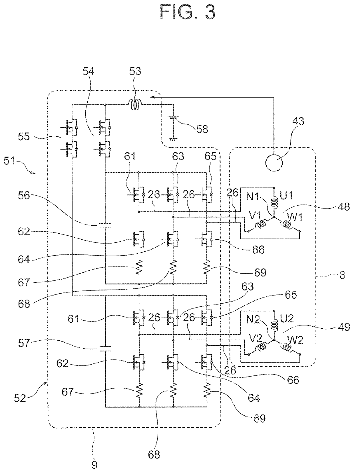
[0088]In the first embodiment, the respective current phase differences between the feeder wires 26 are set at 0° between the U1 phase and the U2 phase, between the V1 phase and the V2 phase, and between the W1 phase and the W2 phase, but instead, the respective current phase differences between the feeder wires 26 may be set at 30° between the U1 phase and the U2 phase, between the V1 phase and the V2 phase, and between the W1 phase and the W2 phase. In other words, in this embodiment, the current phases of the respective feeder wires 26 are set to differ by 30° between the U1 phase and the U2 phase, between the V1 phase and the V2 phase, and between the W1 phase and the W2 phase. All other configurations are identical to the first embodiment.

[0089]Next, the effect exerted on the rotation sensor 44 by the magnetic fields from the respective feeder wires 26 in this embodiment when the rotation sensor 44 and the respective feeder wires 26 have the positional relationship shown in FIG...

third embodiment

[0096]In the first embodiment, a current flows through each of the feeder wires 26, but some of the currents flowing through the respective feeder wires 26 may be permanently stopped. In this embodiment, of the currents flowing through the feeder wires 26 of the U1 phase, the V1 phase, the W1 phase, the U2 phase, the V2 phase, and the W2 phase, currents flow through the feeder wires 26 of the U1 phase, the V1 phase, and the W1 phase, but the currents flowing through the feeder wires 26 of the U2 phase, the V2 phase, and the W2 phase are permanently stopped. In other words, in this embodiment, three-phase power is supplied from the inverter circuit 38 to the first three-phase AC winding 48 alone, of the first and second three-phase AC windings 48, 49, while the power supply from the inverter circuit 38 to the second three-phase AC winding 49 is permanently stopped. All other configurations are identical to the first embodiment.

[0097]Next, the effect of the magnetic fields from the re...


PUM


Abstract

In an electric driving apparatus, a sensor magnet is fixed to a first end portion of a rotary shaft of a motor. A sensor device includes a rotation sensor that detects a magnetic field generated by the sensor magnet. The rotation sensor opposes the sensor magnet in an axial direction of the rotary shaft. A control unit mounted on the motor includes an inverter circuit that is connected to an armature winding of the motor via a plurality of feeder wires. The inverter circuit is disposed in a position further from the sensor magnet than the rotation sensor in the axial direction of the rotary shaft. A shield plate formed from a magnetic material is disposed between the rotation sensor and the inverter circuit.

Description

CROSS REFERENCE TO RELATED APPLICATIONS[0001]This application is a National Stage of International Application No. PCT / JP2015 / 061359 filed Apr. 13, 2015, the contents of all of which are incorporated herein by reference in their entirety.TECHNICAL FIELD[0002]This invention relates to an electric driving apparatus in which a control unit is mounted on a motor.BACKGROUND ART[0003]In a conventional motor, a magnet is mounted on an end portion of a shaft of a rotor, a magnetic sensor is opposed to the magnet on an axis of the shaft, and a rotation angle of the rotor is detected by measuring the magnetism of the magnet using the magnetic sensor, whereupon the motor controls a current supplied to a stator winding. In this type of conventional motor, when a conductor wire through which a current flows, for example, is disposed on the periphery of the magnetic sensor, a noise magnetic field generated by the conductor wire acts on the magnetic sensor, leading to an increase in the likelihood...

Claims


Application Information

Patent Timeline
Patent Type & Authority Patents(United States)
IPC IPC(8): H02K5/15H02K5/00H02K11/33H02K5/22B62D5/04H02K11/00H02K29/08H02K11/215H02K9/22H02K11/23
CPCH02K11/00H02K5/15H02K29/08H02K11/215B62D5/0406H02K5/00H02K11/33H02K9/22H02K11/23H02K9/227
Inventor TAKIZAWA, YUJIAKUTSU, SATORUICHIKAWA, TAKANORIFUSHIE, SHUNSUKE
Owner MITSUBISHI ELECTRIC CORP
Why Eureka
Try Eureka