Reality-based three-dimensional infrastructure reconstruction

Active Publication Date: 2020-04-28
BLACKSHARK AI GMBH
View PDF3 Cites 18 Cited by
  • Summary
  • Abstract
  • Description
  • Claims
  • Application Information

AI Technical Summary

Benefits of technology

[0009]The technique provides numerous advantages. Prior art techniques are generally of two kinds. One prior technique downloads all three-dimensional geometry data from a server computer to a client computer before a simulator or game begins, so that during the game or simulator the geometry data can be rendered on the client computer. No downloading from the server computer is necessary using this technique, but bandwidth requirements can be quite high as is the memory space required on the client computer (and the scene size is limited by memory constraints).
[0012]This technique enables the reconstruction of structures with minimal memory requirements on the client computer in comparison to the memory size of the original source material (aerial footage by satellites or fly-by images). The reconstruction module also has access to a global building script library that contains region- and culture-specific infrastructure templates of buildings, information on the land use of a geographic area, demographic density, etc. The reconstruction module can also operate with limited or sparse data sets, can fill in blank spots in the source material and determine geometry data for areas that have no or partial information, and can generate large scale urban scenes at run-time speed. The invention can reconstruct buildings on a large scale at run-time speed, such as whole cities and urban scenes. The invention is also capable of reconstructing buildings on a planet scale, that is, the viewer can virtually fly around the entire earth and have every registered building be reconstructed once it is close enough.

Problems solved by technology

Prior art products typically only use footprints and heights of buildings, and do not take into account other rich attributes of buildings (such as roof type) or the cultural context of a region or its land use.

Method used


Image

  • Reality-based three-dimensional infrastructure reconstruction
  • Reality-based three-dimensional infrastructure reconstruction
  • Reality-based three-dimensional infrastructure reconstruction

Examples


Embodiment Construction

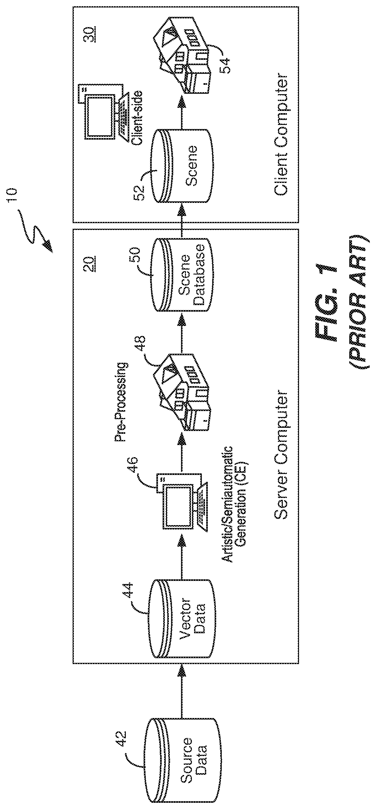
[0034]FIG. 1 illustrates a prior art system 10 for rendering a three-dimensional environment on a client computer 30. Source data 42 is delivered to a server computer 20 in the form of vector data 44. A software engineer takes the vector data and using a semi-automatic process, generates on a computer 46 a 3-D representation of a building 48 (for example) which is stored in a scene database 50 in association with the server computer 20.

[0035]Source data 42 is typically vector data only (such as GIS data), but may also include two-dimensional aerial images, which are used as is to generate a building 48. When vector data is used, it is typically only a building footprint and a height. One example is the modeling software “City Engine,” available from Esri R&D Center, which uses such vector data to model a 3-D city. The output are buildings and other infrastructure of a city which are stored in scene database 50 in preparation for downloading to a client computer in real time as neede...


PUM


Abstract

Two-dimensional aerial images and other geo-spatial information are processed to produce land classification data, vector data and attribute data for buildings found within the images. This data is stored upon a server computer within shape files, and also stored are source code scripts describing how to reconstruct a type of building along with compiled versions of the scripts. A software game or simulator executes upon a client computer in which an avatar moves within a landscape. A classifier classifies a type of building in the shape file to execute the appropriate script. Depending upon its location, a scene composer downloads a shape file and a compiled script is executed in order to reconstruct any number of buildings in the vicinity of the avatar. The script produces a three-dimensional texture mesh which is then rendered upon a screen of the client computer to display a two-dimensional representation of the building.

Description

FIELD OF THE INVENTION[0001]The present invention relates generally to rendering a three-dimensional environment on a computer. More specifically, the present invention relates to reconstructing three-dimensional infrastructure on a client computer before rendering.BACKGROUND OF THE INVENTION[0002]In general, rendering three-dimensional infrastructure (such as buildings) based upon two-dimensional aerial images and other geo-spatial information, and displaying that infrastructure on a computer (whether in a simulator, game or other) is challenging. In particular, streaming such three-dimensional geometric data in real time to the rendering engine of a simulator or game on a computer is problematic. Prior art approaches generate large databases of geometric data that cannot realistically be streamed to a client computer in real time during execution of a simulator or game on the client computer.[0003]In short, there is not enough memory space on a client computer that is executing th...

Claims


Application Information

Patent Timeline
Patent Type & Authority Patents(United States)
IPC IPC(8): G06T15/10G06F8/60G06T17/20G06F8/41G06T3/00H04L29/08H04L29/06
CPCH04L67/06G06F8/44H04L67/18G06F8/60H04L67/38G06T3/0031G06T17/20G06F9/44521G06T17/05G06T15/04G06T19/00G06T2210/36H04L67/52H04L67/131
Inventor THALLER, WOLFGANGRICHTER-TRUMMER, THOMASPUTZ, MICHAELMAIERHOFER, RICHARD
Owner BLACKSHARK AI GMBH
Why Eureka
Try Eureka