Method and apparatus for storing data

Active Publication Date: 2014-07-03
HUAWEI TECH CO LTD
View PDF3 Cites 2 Cited by
  • Summary
  • Abstract
  • Description
  • Claims
  • Application Information

AI Technical Summary

Benefits of technology

The present invention provides a method and apparatus for efficiently storing data to meet high bandwidth requirements without increasing operation frequency beyond the technological limit. The memory system can perform n writes and a single read simultaneously in one clock cycle. The integrated circuit can be designed with single-port SRAMs, which require a small area on silicon, instead of dual-port SRAMs which are larger. The association function can be configured to minimize the difference in occupancy of the memory banks.

Problems solved by technology

However, the dual-port RAM typically consume a silicon area that is in the order of a factor two larger than the area occupied by a single-port RAM of the same memory size.
However, replication of data in memories requires the usage of bigger memories, hence spending more silicon area and higher power than the case where the data is stored only once.
A limitation of the conventional arrangement as shown in FIG. 2 is that the shared memory between the multiplexing unit and the de-multiplexing unit as shown in FIG. 2 is required to support a bandwidth which is n “port bandwidth”, wherein n is the number of the ports.
This poses limitations on the implementation of the shared memory as it needs to support a very high bandwidth and therefore usually needs to operate at a very high frequency relative to the port rate.
The disadvantage of the conventional memory system using a cross bar as illustrated in FIG. 3 is that the scheduler is relatively complex and needs to perform a match between the input ports to the output port to maximize the delivery between inputs and outputs at each switching cycle.
Conventional CLOS based switching system as shown in FIG. 4 generates other problems such as out of order of traffic delivery to the destination ports.
Further the conventional CLOS based switching system is quite complex and difficult to implement.
However, this poses a limitation to the total bandwidth of a single device using this technology as the shared memory is required to support at least double the bandwidth since, at most, all ports are writing to the memory and all ports are reading from the memory at the same time.

Method used


Image

  • Method and apparatus for storing data
  • Method and apparatus for storing data
  • Method and apparatus for storing data

Examples


Embodiment Construction

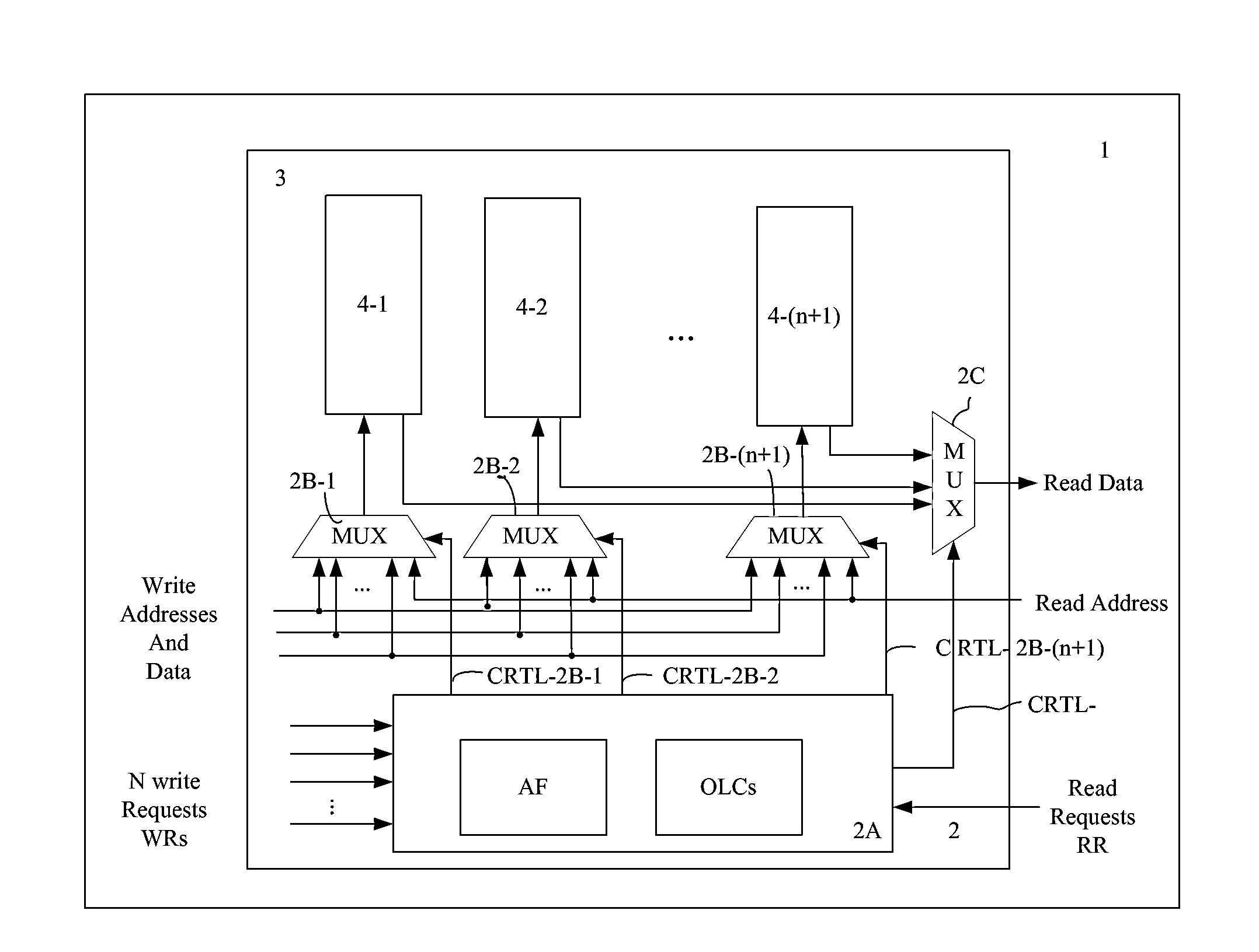
[0064]As can be seen from FIG. 5 showing a possible implementation of a memory system 1 according to a first aspect of the present invention the memory system 1 comprises a control logic 2 and a shared memory 3. The shared memory 3 comprises a predetermined number n+1 of memory banks 4-1, 4-2, 4-3 . . . 4-(n+1) as illustrated in FIG. 5. The shared memory 3 is adapted to store data. The shared memory 3 comprises in the shown implementation of FIG. 5 n+1 memory banks 4-i. As can be seen from FIG. 5 the control logic 2 has individual access to each memory bank 4-i of the shared memory 3. The control logic 2 is adapted to control a memory bank occupancy level MBOL of each memory bank 4-i within the shared memory 3. As can be seen in FIG. 5 the control logic 2 is adapted to receive a number n of write requests WRs from input ports and to receive a read request RR from an output port within a clock cycle of a clock signal CLK applied to the memory system 1. The control logic 2 is adapted ...


PUM


Abstract

A memory system (1) comprising a control logic (2) adapted to receive a number n of write requests (WRs) from input ports and to receive a read request (RR) from an output port within a clock cycle of a clock signal (CLK) applied to said memory system (1), wherein n is a natural number; and n+1 memory banks (4) of a shared memory (3) adapted to store data, wherein the control logic (2) is adapted to control a memory bank occupancy level MBOL of each memory bank (4) such that the differences between memory bank occupancy levels MBOLs of the memory banks (4) are minimized

Description

CROSS-REFERENCE TO RELATED APPLICATIONS[0001]This application is a continuation of International Patent Application No. PCT / CN2011 / 079329, filed on Sep. 5, 2011, which is hereby incorporated by reference in its entirety.TECHNICAL BACKGROUND[0002]The invention relates to a method and apparatus for storing efficiently data by a memory system of an apparatus having ports and in particular by a memory system of a high speed switching device.[0003]High speed, multi-port memory systems are required in many applications, specifically memory systems with a single read port and multiple write ports where all ports can be operational simultaneously. Examples for these applications, but not limited to, are queuing engines as part of switching systems in the networking area or central processing units CPUs in multi-core environments.[0004]Conventional designs of memory systems mainly use single-port or dual-port memories. The single-port memory can be accessed at one address at a time. Accordin...

Claims


Application Information

Patent Timeline
IPC IPC(8): G11C11/413
CPCG11C11/413G06F12/023G06F13/1684G06F2212/2532G06F12/06H04L49/10H04L49/90
Inventor ZECHARIA, RAMISHACHAR, YARON
Owner HUAWEI TECH CO LTD
Why Eureka
Try Eureka