Robotic intraoperative radiation therapy

a robotic system and radiation therapy technology, applied in the field of radiation therapy, can solve the problems of increasing the risk of missing the intended target volume, and achieve the effects of facilitating iort function and operation, facilitating optical guidance of the treatment head, and facilitating ultrasound imaging of the tumor bed

Active Publication Date: 2020-05-12
EMPYREAN MEDICAL SYST INC
View PDF84 Cites 4 Cited by
  • Summary
  • Abstract
  • Description
  • Claims
  • Application Information

AI Technical Summary

Benefits of technology

[0006]According to one aspect, the control system is configured to selectively control the motion of the treatment head in three orthogonal directions. In some scenarios, these operations can involve selectively controlling the position of the treatment head to minimize variations in distance as between an X-ray source of the therapeutic radiation within the treatment head and internal surfaces of the tumor bed during patient breathing activity. According to another aspect, the control system is configured to selectively control a rotation of the treatment head to minimize angular variations of the source of the therapeutic radiation relative to locations comprising the surfaces of the tumor bed under conditions of patient body movement associated with breathing.
[0009]The disclosure also concerns a method for intraoperative radiation therapy. The method involves securing a treatment head on a mounting end of the robotic arm distal from a robotic arm base. At least one X-ray component is included as part of the treatment head; the X-ray component being configured to facilitate generation of therapeutic radiation in the X-ray wavelength range. The method involves detecting with at least one patient motion sensor a movement of a patient body associated with breathing. A control system is provided that is responsive to patient motion data. The control system dynamically controls a position of the treatment head by causing a position variation in at least one of the movable joints comprising the robotic arm. This control of the movable joints is managed so that a relative motion as between the treatment head and a tumor bed internal of the patient is minimized. The dynamic motion control can be performed while using the treatment head to perform IORT.

Problems solved by technology

But conventional EBRT can increase the risk of missing an intended target volume.

Method used


Image

  • Robotic intraoperative radiation therapy
  • Robotic intraoperative radiation therapy
  • Robotic intraoperative radiation therapy

Examples


Embodiment Construction

[0017]It will be readily understood that the components of the systems and methods described herein and illustrated in the appended figures could be arranged and designed in a wide variety of different configurations. Thus, the following more detailed description, as represented in the figures, is not intended to limit the scope of the present disclosure, but is merely representative of certain exemplary scenarios which are useful for understanding the disclosure. While the various aspects are presented in drawings, the drawings are not necessarily drawn to scale unless specifically indicated.

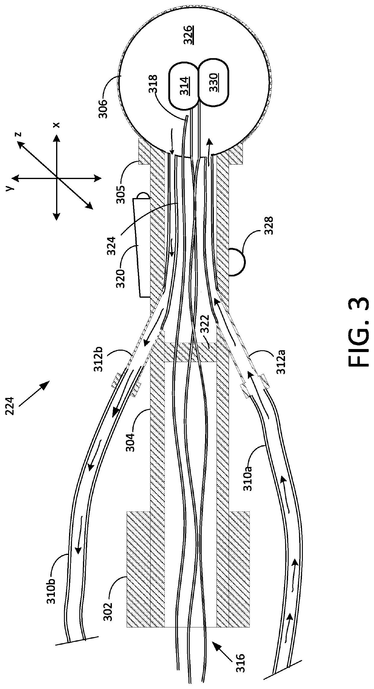
[0018]One type of low energy X-Ray IORT applicator involves a catheter-like device with a balloon tip. After a tumor has been excised, the catheter is inserted into the cavity where the tumor was previously located, a miniature radiation therapy source is then inserted within the balloon into the cavity to deliver radiation to the tumor bed internally and the balloon is inflated with saline suc...


PUM


Abstract

Intraoperative radiation therapy involves a treatment head disposed on a distal end of a robotic arm. An X-ray component included as part of the treatment head generates therapeutic radiation in the X-ray wavelength range. At least one patient motion sensor detects a breathing movement of a patient body. A control system dynamically controls a position of the treatment head by causing a position variation in at least one of the movable joints comprising the robotic arm. This movement is managed so that a relative motion as between the treatment head and a tumor bed internal of the patient is minimized.

Description

CROSS-REFERENCE TO RELATED APPLICATIONS[0001]This application claims priority to U.S. patent application Ser. No. 62 / 361,715, filed Jul. 13, 2016. The contents of the above application is incorporated by reference its entiretyBACKGROUNDStatement of the Technical Field[0002]The inventive arrangements relate to radiation therapy, and more particularly to robotic systems and methods for intraoperative radiation therapy.Description of the Related Art[0003]Cancer surgery can involve removal of a cancerous tumor and some normal tissue surrounding the tumor. For example, Breast Conserving Surgery (BCS) is a type of cancer surgery in which a cancerous lump and part of the surrounding breast tissue (as opposed to the entire breast) is removed during surgery. The surgery is usually followed by a moderate-dose radiation therapy which is intended to eradicate any traces of cancerous tissue from a tumor bed (vascular and stromal tissue that surrounds a cancerous tumor). Radiotherapy techniques c...

Claims


Application Information

Patent Timeline
Patent Type & Authority Patents(United States)
IPC IPC(8): A61N5/10A61B90/50A61B34/20A61B34/30A61B90/00
CPCA61N5/1049A61B90/50A61B90/37A61B34/20A61N5/1083A61N5/1007A61B34/30A61N2005/1061A61N2005/1008A61B2034/301A61B2090/3784A61B2090/378A61N5/1015A61N2005/1091
Inventor FISHMAN, KALMAN
Owner EMPYREAN MEDICAL SYST INC
Why Eureka
Try Eureka