Control system

a control system and control device technology, applied in the direction of electric generator control, dynamo-electric converter control, dynamo-electric gear control, etc., can solve the problem that the normal determination cannot be made in the initial check of the other control device, and achieve the effect of suppressing the situation

Active Publication Date: 2020-05-26
DENSO CORP
View PDF14 Cites 0 Cited by
  • Summary
  • Abstract
  • Description
  • Claims
  • Application Information

AI Technical Summary

Benefits of technology

[0007]It is an object of the present disclosure to provide a control system that can properly start the drive control of a rotary electric machine after an initial check.
[0010]On the other hand, there is a possibility that the initial check takes a longer time than assumed or the initial check is not ended. In this case, if the end of the initial check of another control device is endlessly awaited, the drive of the rotary electric machine cannot be started. In this respect, in the above configuration, since the drive control of the rotary electric machine is started after a lapse of the predetermined time from a predetermined time point in the initial check of the corresponding control device, it is possible to suppress the situation of endlessly awaiting the end of the initial check of another control device. Therefore, it is possible to suppress the situation of delaying the start of the drive control of the rotary electric machine while suppressing the situation of being unable to make a normal determination in the initial check.

Problems solved by technology

In the case where the drive control of the rotary electric machine is started with the end of the initial check of the control device as a trigger, if the initial check of another control device is not ended, there is a possibility that a normal determination cannot be made in the initial check of the other control device.

Method used


Image

  • Control system
  • Control system
  • Control system

Examples


first embodiment

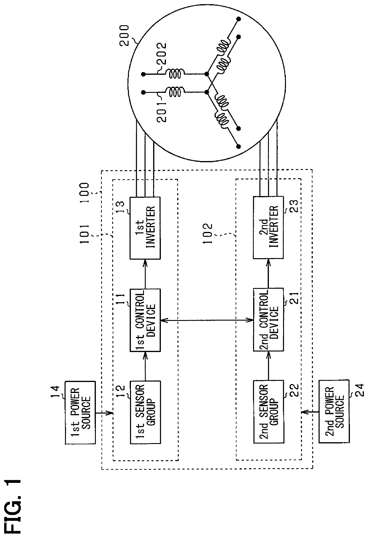
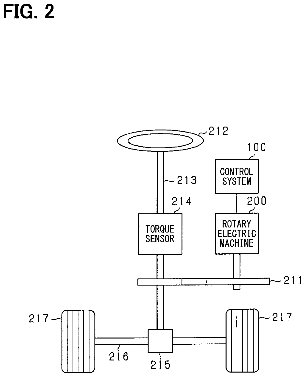
[0026]A control system 100 according to the present embodiment is mounted on a vehicle, and used to control a rotary electric machine 200 connected to the steering device of the vehicle so that the steering device functions as an electric power steering. The configuration of the control system 100 according to the present embodiment will be described with reference to FIG. 1.

[0027]The control system 100 has a first control system 101 and a second control system 102. The rotary electric machine 200 controlled by the control system 100 has a first winding set 201 and a second winding set 202 each having three-phase windings of U, V, and W phases. The control of current conduction of the first winding set 201 is performed by the first control system 101. The control of current conduction in the second winding set 202 is performed by the second control system 102.

[0028]The first control system 101 includes a first control device 11. The first control device 11 is a microcomputer having ...

second embodiment

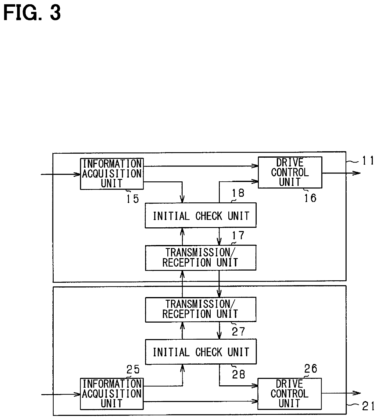
[0074]The overall configuration of the control system 100 according to the present embodiment is the same as in the first embodiment, and a condition for starting the initial check is partially different from that in the first embodiment. In the present embodiment, the first control device 11 starts the initial check, with the transmission of the start signal to the second control device 21 as a trigger, and the second control device 21 starts the initial check, with the reception of the start signal from the first control device 11 as a trigger. That is, unlike in the first embodiment, the start signal of the initial check is not transmitted from the second control device 21 to the first control device 11.

[0075]In this case, it takes a certain time from when the first control device 11 transmits the start signal to when the second control device 21 receives the start signal and starts the initial check. Accordingly, a given waiting period from the transmission of the start signal t...

third embodiment

[0089]The configuration of a control system 100 according to the present embodiment is partially different from that in the first embodiment. FIG. 12 is an overall block diagram of the control system 100 according to the present embodiment.

[0090]The control system 100 includes a signal transmitter 103 in addition to the first control system 101 and the second control system 102. The signal transmitter 103 is a transmission element for transmitting a signal if a predetermined condition is satisfied, and transmits the signal to the first control device 11 and the second control device 21. The signal transmitted by the signal transmitter 103 is a start signal for instructing the start of the initial check. The signal transmitter 103 may be an IC or an LSI.

[0091]The condition of transmitting the start signal by the signal transmitter 103 is, for example, to satisfy both a condition that the supply of power from the first power source 14 to the first control system 101 is started and a c...


PUM


Abstract

A control system includes a plurality of control devices each including an initial check unit that performs an initial check before drive control of a rotary electric machine, a transmission / reception unit that transmits / receives an end signal indicating that the initial check is ended, and a drive control unit that performs the drive control of the rotary electric machine after the initial check. The drive control unit starts the drive control of the rotary electric machine when the initial check of the corresponding control device is ended and the end signal is acquired from another control device, and starts the drive control of the rotary electric machine after a lapse of a predetermined time from the start of the initial check of the corresponding control device when the initial check of the corresponding control device is ended and the end signal is not acquired from the another control device.

Description

CROSS REFERENCE TO RELATED APPLICATION[0001]This application is based on Japanese Patent Application No. 2016-53700 filed on Mar. 17, 2016, the disclosure of which is incorporated herein by reference.TECHNICAL FIELD[0002]The present disclosure relates to a control system for controlling a rotary electric machine.BACKGROUND ART[0003]Conventionally, a control system for performing the drive control of a rotary electric machine performs an initial check to determine whether or not the rotary electric machine operates normally by conducting current to the winding of the rotary electric machine, before the drive control of the rotary electric machine. Patent Literature 1 describes a control system for performing such an initial check.[0004]The control system described in Patent Literature 1 includes two microcomputers. Upon starting an operation, each microcomputer first performs an initial check, and then waits until the initial check of the other microcomputer is ended. If it is determ...

Claims


Application Information

Patent Timeline
Patent Type & Authority Patents(United States)
IPC IPC(8): H02P21/34H02P6/20B62D5/04H02P27/06H02P25/22H02P21/22
CPCH02P6/20B62D5/046H02P21/22H02P21/34H02P25/22B62D5/0403H02P27/06
Inventor NAKAMURA, KOICHIKURAMITSU, SHUJIOKA, ATSUKO
Owner DENSO CORP
Why Eureka
Try Eureka