Surface treatment device and surface treatment method

a surface treatment and treatment device technology, applied in blast generation devices, abrasion devices, manufacturing tools, etc., can solve problems such as complicated device configuration, and achieve the effects of preventing polishing agents, efficient recovery of polishing agents, and stable blast spa

Active Publication Date: 2020-06-02
NISSAN MOTOR CO LTD
View PDF11 Cites 2 Cited by
  • Summary
  • Abstract
  • Description
  • Claims
  • Application Information

AI Technical Summary

Benefits of technology

[0008]In order to solve the problem described above, an object of the present invention is to provide a surface treatment device and a surface treatment method capable of efficiently recovering the polishing agent without complicating the device configuration.
[0011]According to the surface treatment device and the surface treatment method described above, the space into which polishing agent is sprayed is surrounded by an air curtain. Thus, the blast space in which a blast treatment is carried out can be formed within a closed space. Therefore, it is possible to prevent the polishing agent from being discharged from the blast space to the outside. Additionally, the auxiliary air is injected toward the material to be treated between the air curtain and the suction air. Thus, auxiliary air is injected onto the polishing agent that remains between the air curtain and the suction air. At this time, since the pressure of the auxiliary air is lower than the pressure for forming the air curtain, it is possible to form a stable blast space. As a result, the remaining polishing agent is released from a static condition and recovered by the suction air via the suction hole. Therefore, it is possible to efficiently recover the polishing agent. In addition, since a treatment chamber to enclose the injection nozzle and all of the material to be treated need not be provided, it is possible to avoid a complex device configuration. Therefore, it is possible to provide a surface treatment device and a surface treatment method capable of efficiently recovering the polishing agent without resorting to a complex device configuration.

Problems solved by technology

However, since a treatment chamber for enclosing the material to be treated is required in the method disclosed in Patent Document 1, there is the problem that the device configuration becomes complicated.

Method used


Image

  • Surface treatment device and surface treatment method
  • Surface treatment device and surface treatment method
  • Surface treatment device and surface treatment method

Examples


Embodiment Construction

[0021]Embodiments of the present invention will be explained below with reference to the appended drawings. In the explanations of the drawings, identical elements are given the same reference symbols and redundant explanations are omitted. The dimensional ratios used in the drawings may be exaggerated for the sake of convenience of the explanation and may differ from the actual ratios.

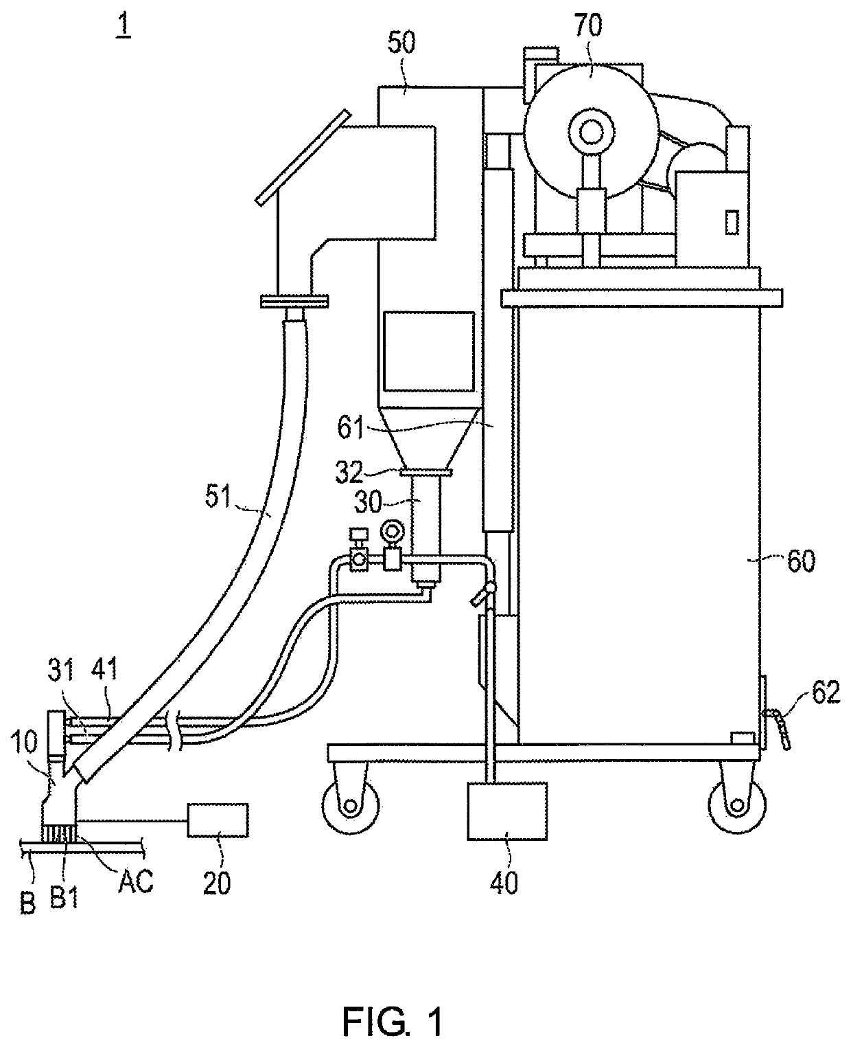
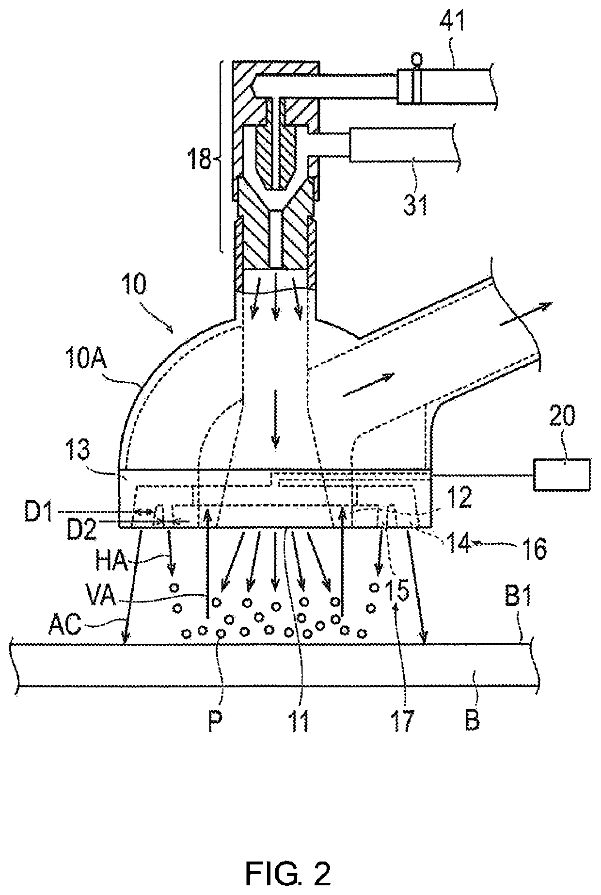
[0022]The surface treatment device 1 according to the present embodiment is a vacuum blast device. In general, the surface treatment device 1 sprays a polishing agent onto a material B to be treated and subjects the surface B1 of the material B to be treated to blast treatment to thereby roughen the surface B1 of the material B to be treated. By roughening the surface B1 of the material B to be treated, the adhesion area increases and the bonding strength by means of the adhesive is improved. In addition, the surface treatment device 1 recovers the polishing agent sprayed onto the material B to be tre...


PUM

PropertyMeasurementUnit
pressureaaaaaaaaaa
pressureaaaaaaaaaa
pressureaaaaaaaaaa

Abstract

A surface treatment device includes a vacuum blast head, an air curtain-forming unit and an auxiliary air injection unit. The vacuum blast head includes an injection nozzle and a suction hole. The injection nozzle injects a polishing agent used for blast treatment on a surface of a material to be treated. The suction hole sucks up the injected polishing agent with suction air. The air curtain-forming unit injects air toward the surface of the material to be treated to form an air curtain that surrounds the injected polishing agent. The auxiliary air injection unit injects auxiliary air between the air curtain and the suction air toward the material to be treated at a lower pressure than the air that forms the air curtain.

Description

CROSS-REFERENCE TO RELATED APPLICATIONS[0001]This application is a U.S. National stage application of International Application No. PCT / JP2015 / 081500, filed on Nov. 9, 2015.BACKGROUNDField of the Invention[0002]The present invention relates to a surface treatment device and a surface treatment method.Background Information[0003]In recent years, for reasons of weight reduction, carbon fiber-reinforced plastic (CFRP) is being used in vehicle body structures. When manufacturing a vehicle body structure from CFRP, members are bonded with an adhesive. In this case, as a pretreatment for adhesion, the surface of the material to be treated as a member is subjected to blast treatment by means of a vacuum blast treatment.[0004]In a vacuum blast treatment, a polishing agent is injected onto the material to be treated to roughen the surface of the material to be treated, to thereby increase the adhesion area and improve the bonding strength. In addition, the polishing agent sprayed onto the ma...

Claims


Application Information

Patent Timeline
Patent Type & Authority Patents(United States)
IPC IPC(8): B24C5/04B24C5/02B24C1/06B24C9/00
CPCB24C1/06B24C5/04B24C5/02B24C9/00
Inventor USUI, KATSUHIRONAGAO, TAKESHI
Owner NISSAN MOTOR CO LTD
Why Eureka
Try Eureka