Electronic device having wireless power transmitting/receiving conductive pattern

a technology of electrical components and electronic devices, applied in the direction of printed inductance, inductance association, printed circuit non-printed electric components, etc., can solve the problems of increasing the surface temperature of the electronic device, limiting usability, increasing the surface temperature of the wireless power transmitting electronic device or the wireless power receiving electronic device, etc., to achieve accurate measurement of temperature and increase the thickness of the electronic device

Active Publication Date: 2020-06-09
SAMSUNG ELECTRONICS CO LTD
View PDF6 Cites 0 Cited by
  • Summary
  • Abstract
  • Description
  • Claims
  • Application Information

AI Technical Summary

Benefits of technology

[0009]Various embodiments of the present disclosure may provide an electronic device in which a temperature sensor can be mounted without an increase in the thickness of the electronic device.
[0010]Further, various embodiments of the present disclosure may provide a method and device that can accurately measure temperature in order to effectively control the heat dissipation of an electronic device during wireless power transmission / reception, thereby effectively controlling the heat dissipation based on the accurate temperature.
[0014]According to the various embodiments of the present disclosure, a temperature sensor can be mounted in an electronic device without an increase in the thickness of the electronic device.
[0015]In addition, the various embodiments of the present disclosure may provide a method capable of accurately measuring the temperature of a wireless power transmitting / receiving conductive pattern using a temperature sensor mounted in an electronic device.

Problems solved by technology

When an electronic device that supports wireless power transmission / reception transmits and receives power in a wireless manner, the surface temperature of the electronic device may increase, which causes a limitation of usability.
For example, when misalignment occurs between a wireless power transmitting electronic device and a wireless power receiving electronic device, heat energy may be generated due to degradation in power transmission efficiency, which causes an increase in the surface temperature of the wireless power transmitting electronic device or wireless power receiving electronic device.
Although the wireless power transmitting / receiving electronic devices have temperature sensors (thermistors) in order to measure the internal temperature thereof, the temperature sensors may fail to accurately measure the surface temperature of the electronic devices that is generated during wireless power transmission / reception because the temperature sensors are not located close to conductive patterns for the wireless power transmission / reception.

Method used


Image

  • Electronic device having wireless power transmitting/receiving conductive pattern
  • Electronic device having wireless power transmitting/receiving conductive pattern
  • Electronic device having wireless power transmitting/receiving conductive pattern

Examples


Embodiment Construction

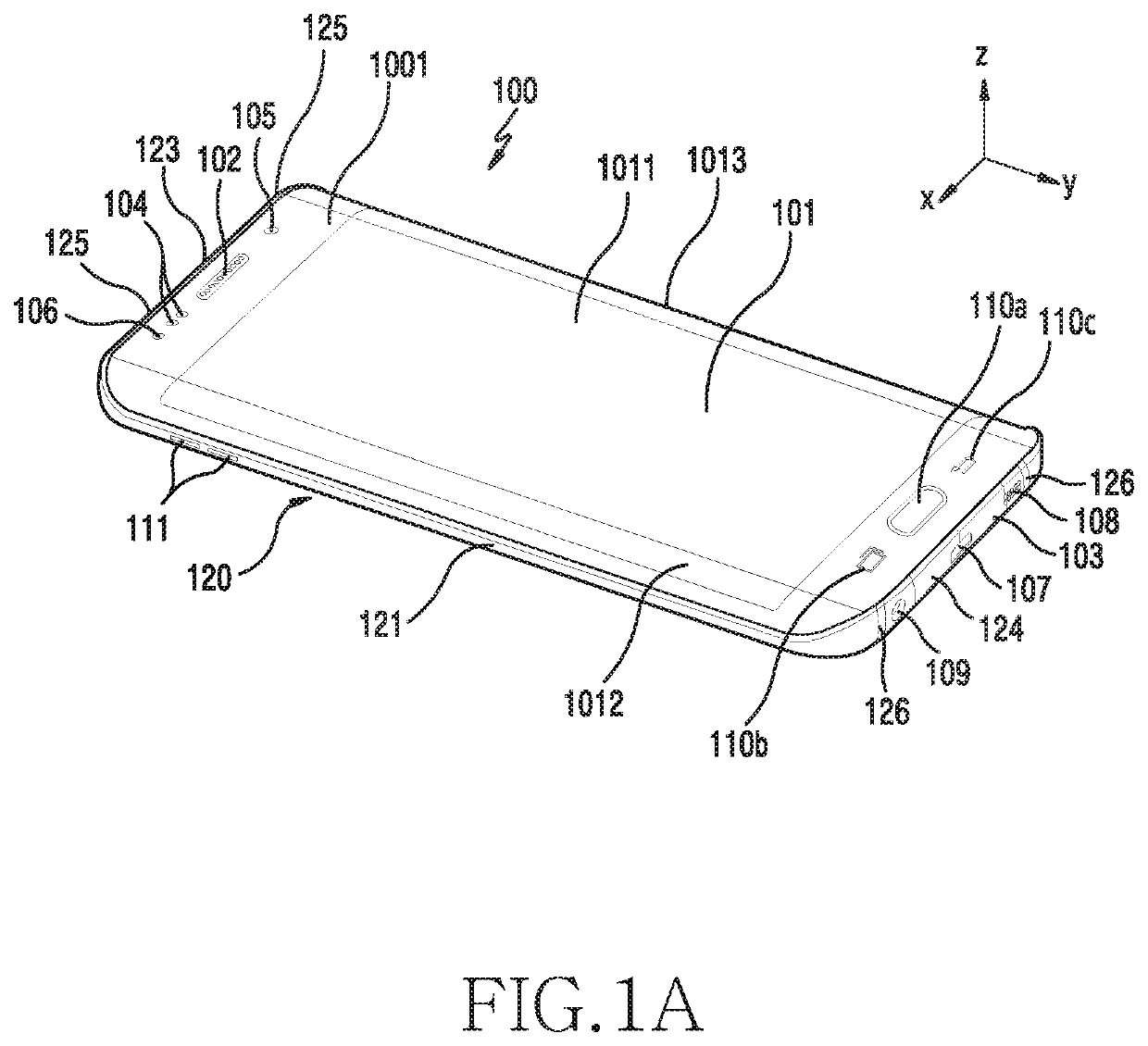
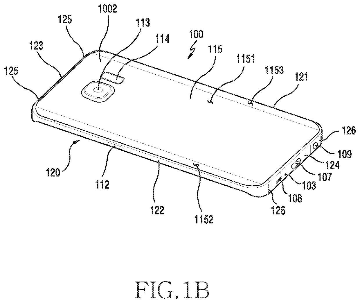
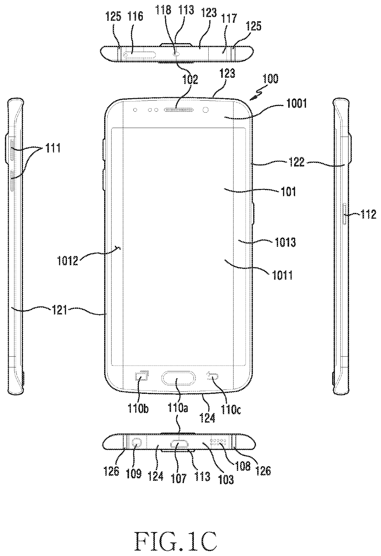
[0038]FIGS. 1A through 15, discussed below, and the various embodiments used to describe the principles of the present disclosure in this patent document are by way of illustration only and should not be construed in any way to limit the scope of the disclosure. Those skilled in the art will understand that the principles of the present disclosure may be implemented in any suitably arranged electronic devices. The disclosure is described with reference to the accompanying drawings. The disclosure may be changed and may include various examples, and specific examples are exemplarily described and related detailed descriptions are made in the specification. However, it should be understood that the various examples of the disclosure are not limited to a specific embodied form and include all modifications and / or equivalents or substitutions that fall within the spirit and technical scope of the disclosure. In the drawing, like reference numerals are used for like elements.

[0039]Expres...


PUM

PropertyMeasurementUnit
power transmission frequencyaaaaaaaaaa

Abstract

Various embodiments of the present disclosure may provide an electronic device that includes: a first plate directed in a first direction, a second plate directed in a second direction opposite to the first direction, and a side member configured to surround at least a part of the space between the first and second plates; a first printed circuit board (PCB) that is disposed between the first and second plates and includes at least one processor; a second printed circuit board (PCB) that is disposed between the first printed circuit board and the second plate and includes at least one antenna pattern; and a temperature sensor disposed to measure the temperature of at least a part of the second printed circuit board. Other various embodiments are possible.

Description

CROSS-REFERENCE TO RELATED APPLICATIONS[0001]This application is a continuation of application Ser. No. 15 / 236,374, filed Aug. 12, 2016, which priority to Korean Application Serial No. 10-2015-0114199, filed Aug. 12, 2015, the disclosures of which are hereby incorporated by reference.BACKGROUND1. Field[0002]Various embodiments of the present disclosure relate to a temperature sensor mounting structure for detecting the temperature of a wireless charging coil.2. Description of Related Art[0003]Wireless charging devices (e.g., systems) may convert electrical energy into an electromagnetic wave form of energy to wirelessly transfer the energy as a load without a transmission line.[0004]Wireless charging may be mainly classified into a charging type using electromagnetic induction and a charging type using magnetic resonance. The electromagnetic induction type charging technique is a method of charging a battery while a charging pad and two coils of an electronic device generate an indu...

Claims


Application Information

Patent Timeline
Patent Type & Authority Patents(United States)
IPC IPC(8): H02J50/90H01F38/14H05K1/16H02J50/12H04B5/00H05K1/18H02J7/02H05K1/02H04M1/02H05K3/42G01K13/00
CPCH04B5/0081H02J50/12H05K1/165H01F38/14H04B5/0031H02J50/90H04B5/0037H05K1/181G01K13/00H05K1/0298H04M1/0262H05K2201/10037H05K1/0203H04M2250/12H05K3/429H05K2201/10151H05K2201/1003H04M1/0277H02J7/00034
Inventor JANG, KIYOUNPARK, CHULWOOSEO, HYUNDEOKJANG, SE-YOUNGCHO, CHI-HYUN
Owner SAMSUNG ELECTRONICS CO LTD
Why Eureka
Try Eureka